
Space Time Block Code Communications with Co-Operative Relays

a technology of spacetime block code and co-operation relay, which is applied in the direction of frequency-division multiplex, repeater circuit, transmission monitoring, etc., can solve the problems of high network cost, achieve the effect of enhancing reducing the overall cost of the network, and improving the quality of received signals

Inactive Publication Date: 2008-01-31
APPLE INC
View PDF11 Cites 43 Cited by
  • Summary
  • Abstract
  • Description
  • Claims
  • Application Information

AI Technical Summary

Benefits of technology

[0004] This invention describes a method of employing STBCs, such as Alamouti STBCs, in combination with cooperative relaying in a multihop network to further improve the quality of the received signal. This invention provides for a further enhancement of the received signal quality in an efficient manner requiring minimum complexity in the respective nodes. This means that fewer relays are required for a given performance, thus reducing the overall cost of the network. Only one antenna is required at each node (i.e., base station, relay and user terminal) although extension to multiple antennas is possible. The invention also describes an efficient method of arranging the transmissions of the various nodes (base station, relay and user terminal) to avoid violating causality and to provide adequate time for each node to process the received signals in an efficient manner.
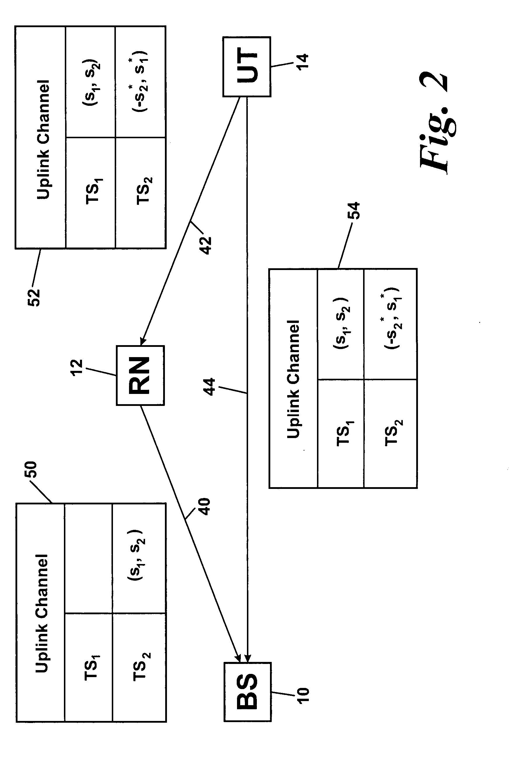
[0020] The invention to be described herein affords several advantages. The base station (BS) only needs to transmit on the “downlink” channel and receive on the “uplink” channel. The relay is only required to transmit on the “downlink” channel and to receive on the “uplink” channel, although it may need to do so simultaneously in some embodiments in an FDD system. The RN (relay node) is therefore very simple and potentially inexpensive. The user terminal (UT) is only required to transmit on the “uplink” channel and to receive on the “downlink” channel, although it may need to do so simultaneously in some embodiments in an FDD system. The most significant modification in practical products is to enable the UT and BS to decode Alamouti STBCs and optionally to store and subsequently combine signals from the BS and UT respectively with those from the RN, providing additional diversity; however, this is optional and so UTs that do not have this capability are not excluded from the system.

Problems solved by technology

A number of alternative cooperative relaying schemes have been proposed but these involve multiple relays acting in parallel in each path, which means more relays are required, resulting in a higher network cost.

Method used


Image

  • Space Time Block Code Communications with Co-Operative Relays
  • Space Time Block Code Communications with Co-Operative Relays
  • Space Time Block Code Communications with Co-Operative Relays

Examples


Embodiment Construction

[0029] The following is a description of the best mode of practicing the invention known to the inventor.

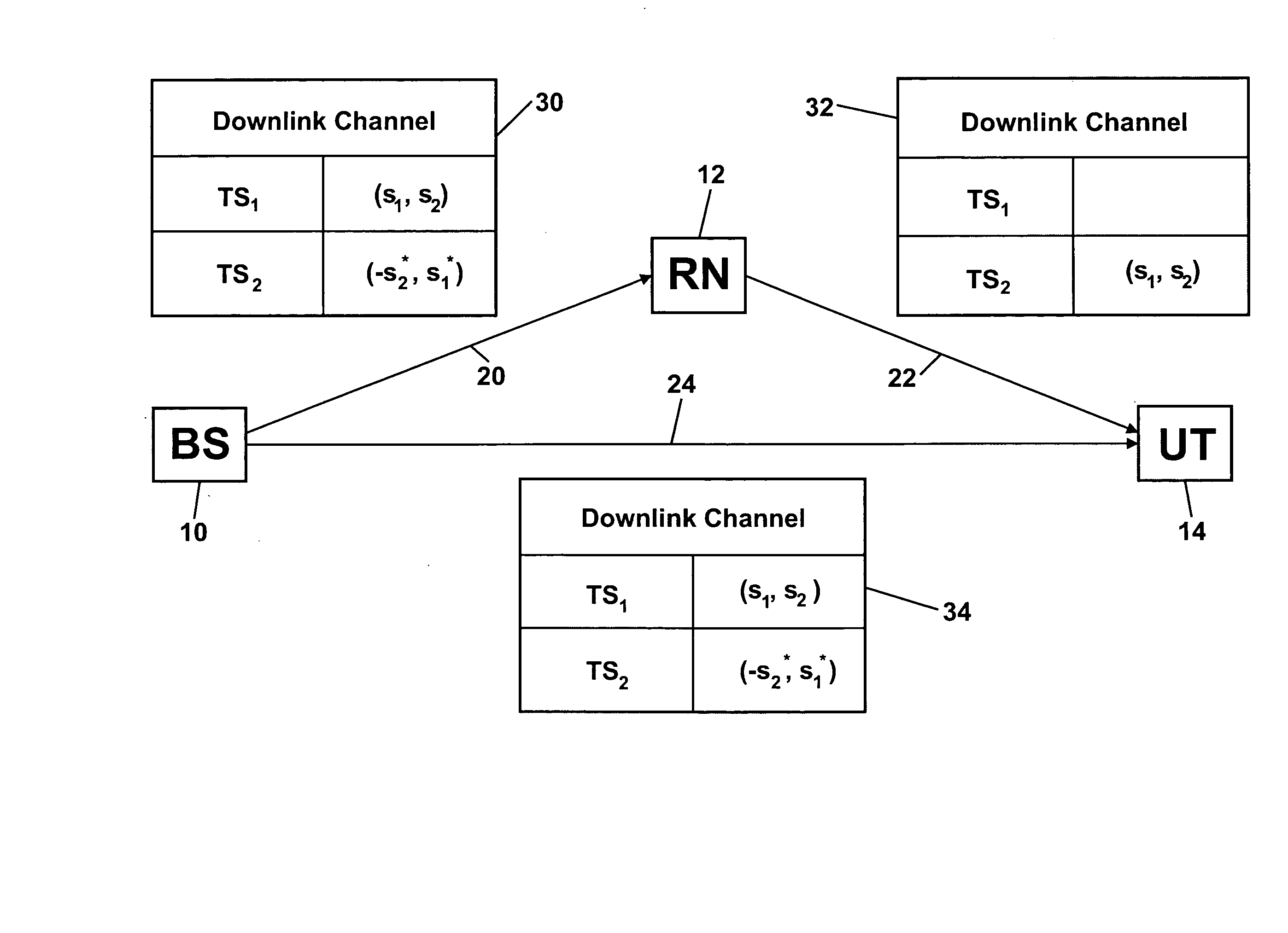
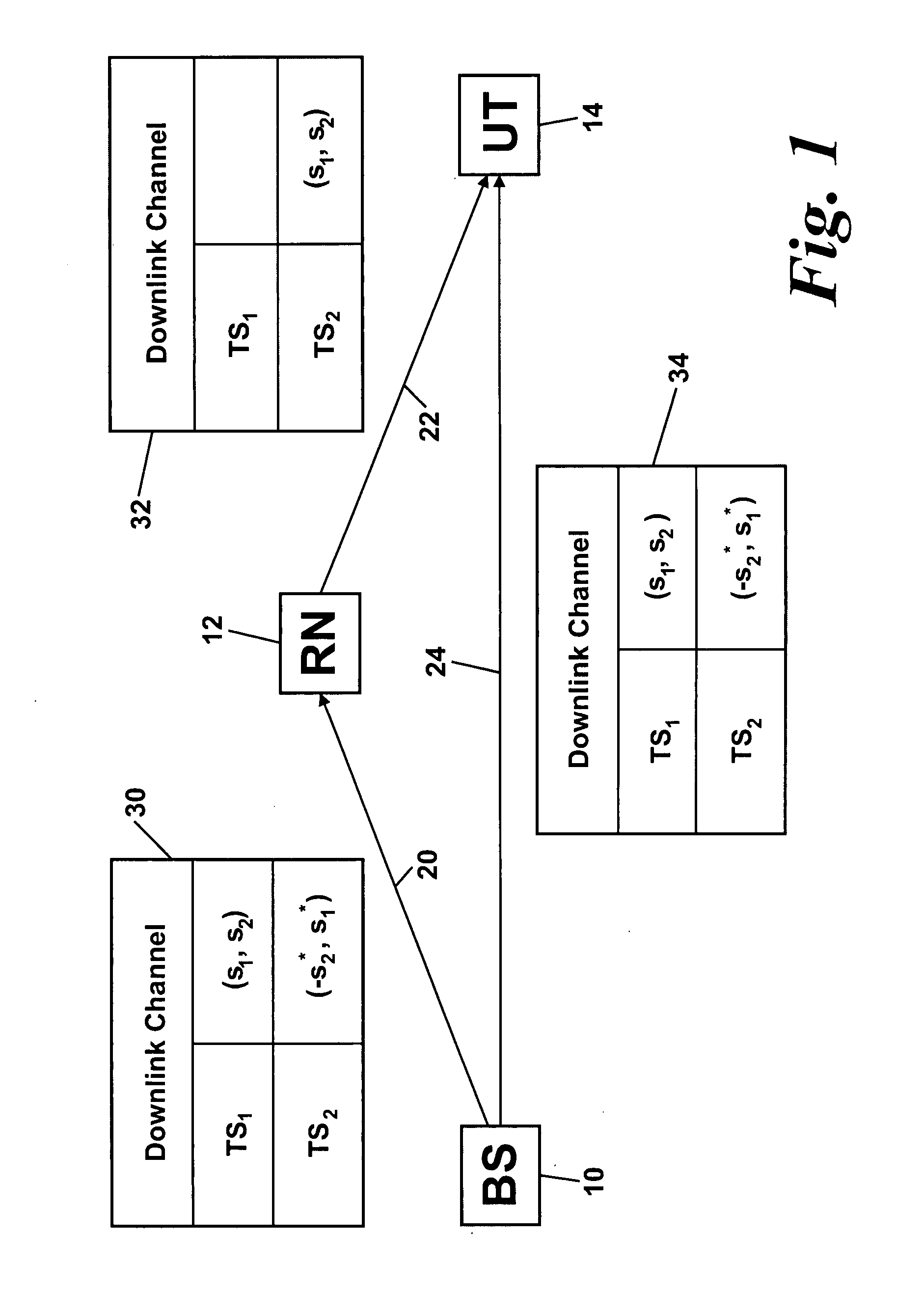
[0030]FIG. 1 shows transmission on the downlink in accordance with the present invention. A base station BS 10 transmits a downlink signal which is received by a relay node RN 12 as downlink signal 20 and by a user terminal UT 14 as downlink signal 24. RN 12 also transmits a downlink signal 22 which is received by UT 14. Tables 30, 32, and 34 show the contents of downlink signals 20, 22 and 24 respectively. Each signal comprises two downlink channels—timeslot TS1 and timeslot TS2.

[0031] The contents of downlink signals 20 and 24 transmitted from BS 10 comprise two symbols (s1, s2) in TS1 and a function of the two symbols (−s2*, s1*) in TS2 (where x* represents the complex conjugate of x). If these symbols (s1, s2) and (−s2*, s1*) were transmitted in the same downlink channel (e.g., in TS1) from two separate antennas of the base station for reception at a single antenna of a use...


PUM


Abstract

Methods, systems and apparatuses are provided for transmitting and receiving space-time block coded data in a wireless communications system with co-operative relays. A source node transmits RF signals representing first and second sets of data symbols in respective first and second channels (in time frequency code or any combination) of a wireless communications system, the first and second sets of data symbols being for transmission from separate antennas respectively according to a space-time block code. A relay node receives the RF signals representing the first set of data symbols in the first channel and transmits RF signals representing the first set of data symbols in the second channel. A destination node received the RF signals representing the second set of data symbols from the source node and the RF signals representing the first set of data symbols from the relay node. This enables decoding of the received RF signals representing the first and second sets of data symbols according to the space-time block code.

Description

FIELD OF THE INVENTION [0001] The present invention relates to methods, systems and apparatuses for transmitting and receiving space-time block coded data in a wireless communications system with cooperative relays. BACKGROUND OF THE INVENTION [0002] In a conventional cellular wireless system, a base station communicates directly with a user terminal. If two antennas are available at the base station, a space time block code (STBC), such as an Alamouti STBC, may be used to obtain diversity gain, thus improving the quality of the received signal. A multihop network differs from a conventional cellular network in that one or more relays may be included in the path between a base station and a user terminal. Multihop diversity, sometimes known as cooperative relaying, combines the signals from the source (e.g., base station) and a relay at the destination (e.g., user terminal) to improve the quality of the received signal. The purpose of a multihop system is to enhance the signal quali...

Claims


Application Information

Patent Timeline
Patent Type & Authority Applications(United States)
IPC IPC(8): H04B7/212
CPCH04B7/15592H04L1/0625H04L1/0668H04L47/826H04L1/04H04L1/0631H04L5/0039H04L2001/0097
Inventor NADEN, JAMES MARK
Owner APPLE INC
Learn More