
Method for designing spectacle lens, spectacle lens, and spectacles

a technology of spectacle lens and design method, which is applied in the field of designing spectacle lens, spectacle lens, and spectacles, can solve the problem of not providing a method for creating spectacle lens that corrects astigmatism in wraparound-type spectacle frame, and achieve the effect of clear vision without blurriness

Active Publication Date: 2008-01-31
HOYA LENS MFG PHILIPPINES
View PDF12 Cites 28 Cited by
  • Summary
  • Abstract
  • Description
  • Claims
  • Application Information

AI Technical Summary

Benefits of technology

[0009] Accordingly, the present invention provides a method for designing a spectacle lens not only capable of correcting effects of bend angle and pantoscopic angle, but also has cylindrical power for a spectacle lens mounted in a spectacle frame having a large bend angle.
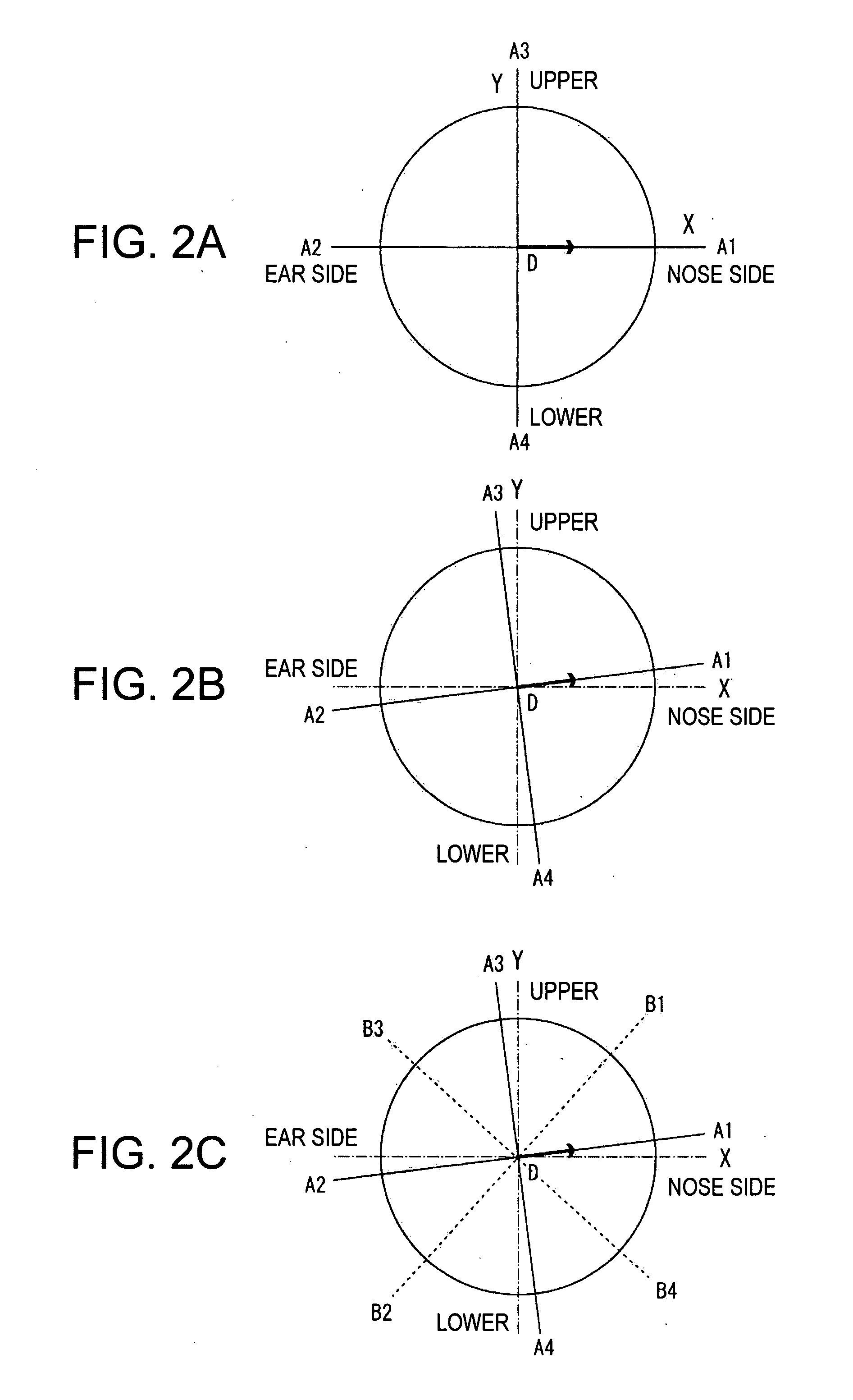
[0015] In this method for designing the spectacle lens for establishing reference meridians according to the first aspect of the present invention, when astigmatic power for correcting astigmatism is added, the effect caused by the variation of target dioptric power in accordance with the angles of the meridians can be corrected simultaneously while correcting the effect of the bend angle only by adding astigmatic reference meridians which indicates the direction of the astigmatic axis to the reference meridians.
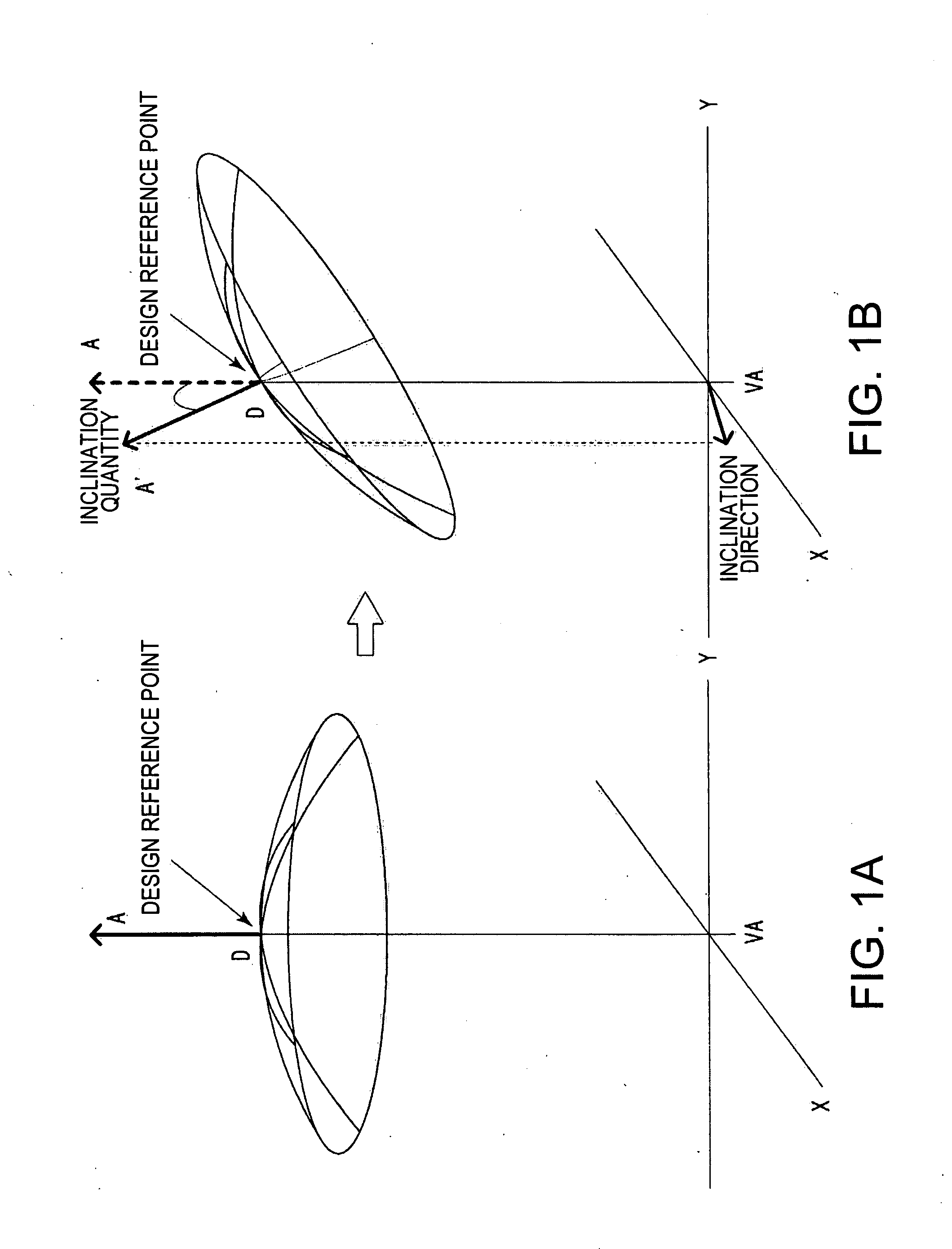
[0017] When the spectacle frame has an inclination angle which causes an effect larger than an ignorable level, the astigmatic power and prismatic power are added to the entire refractive surface so as to cancel the effect caused by the inclination angle at the design reference point. In addition, the effect of the bend angle and the effect of the inclination angle can be simultaneously corrected by accounting for the bend angle and the inclination angle in establishing the first reference meridian. This is accomplished by including the aspherical surface quantities for correcting the effect of the inclination angle.
[0021] According to the above aspects of the present invention, prismatic power and aberration caused by the bend angle and the resulting astigmatic power are canceled, and therefore clear vision without blurriness can be obtained.

Problems solved by technology

Although individuals with astigmatism desire to use wraparound-type spectacle frames, this technique does not provide a method for creating a lens that corrects astigmatism in wraparound-type spectacle frames.

Method used


Image

  • Method for designing spectacle lens, spectacle lens, and spectacles
  • Method for designing spectacle lens, spectacle lens, and spectacles
  • Method for designing spectacle lens, spectacle lens, and spectacles

Examples


embodiment 1

[0063]FIG. 5 shows visual aberrations, visual average dioptric power distributions, and visual aberrations without prescribed astigmatism obtained by removing the prescribed astigmatism dioptric power from the visual aberrations for the lenses No. 1 through No. 4. The results in the figures are all viewed from the rear surface side of the lens, and the geometric centers of the results correspond to the design reference point. The contour interval is 0.25 dioptre.

[0064] Lens No. 1 is a basic lens attached to a frame having a bend angle of 180 degrees and an inclination angle of zero degrees.

[0065] Lens No. 2 is a basic lens inclined with its center located at the distance visual point on the rear surface and attached to a frame having a bend angle of 212 degrees and an inclination angle of zero degrees. The distance visual point on the rear surface corresponds to the design reference point.

[0066] Lens No. 3 is a lens after correction of the effect of the bend angle at the design r...

embodiment 2

[0068] According to an exemplary embodiment of the present invention, FIG. 6 shows visual aberrations, visual average dioptric power distributions, and visual aberrations without prescribed astigmatism obtained by removing prescribed astigmatism dioptric power from the visual aberrations for lenses No. 5 through No. 8. The results in the figure are all viewed from the rear surface side of the lens, and the geometric centers of the results correspond to the design reference point. The contour interval is 0.25 dioptre.

[0069] Lens No. 5 is a basic lens attached to a frame having a bend angle of 180 degrees and an inclination angle of zero degrees (the same as lens No. 1).

[0070] Lens No. 6 is a basic lens inclined with its center located at the distance visual point on the rear surface and attached to a frame having a bend angle of 210.91 degrees and an inclination angle of 4.14 degrees (inclination direction: 345 degrees, inclination angle: 16 degrees). The distance visual point on t...


PUM


Abstract

A method of correcting the effects of a bend angle of 200 degrees or larger of spectacle frames, and astigmatism correcting characteristics in such spectacle frames. An exemplary embodiment of the present invention includes a design method for a spectacle lens mounted in a spectacle frame having a bend angle of 200 degrees or larger including an astigmatic power adding step, on the object side refractive surface or eyeball side refractive surface of the spectacle lens, for canceling astigmatic aberration caused by the bend angle of the spectacle frame, at a design reference point of the spectacle lens, and a step setting prismatic power by tilting the refractive surface, which is on an object side or an eyeball side, of the spectacle lens for canceling prismatic power caused by the bend angle of the spectacle frame, at the design reference point of the spectacle lens.

Description

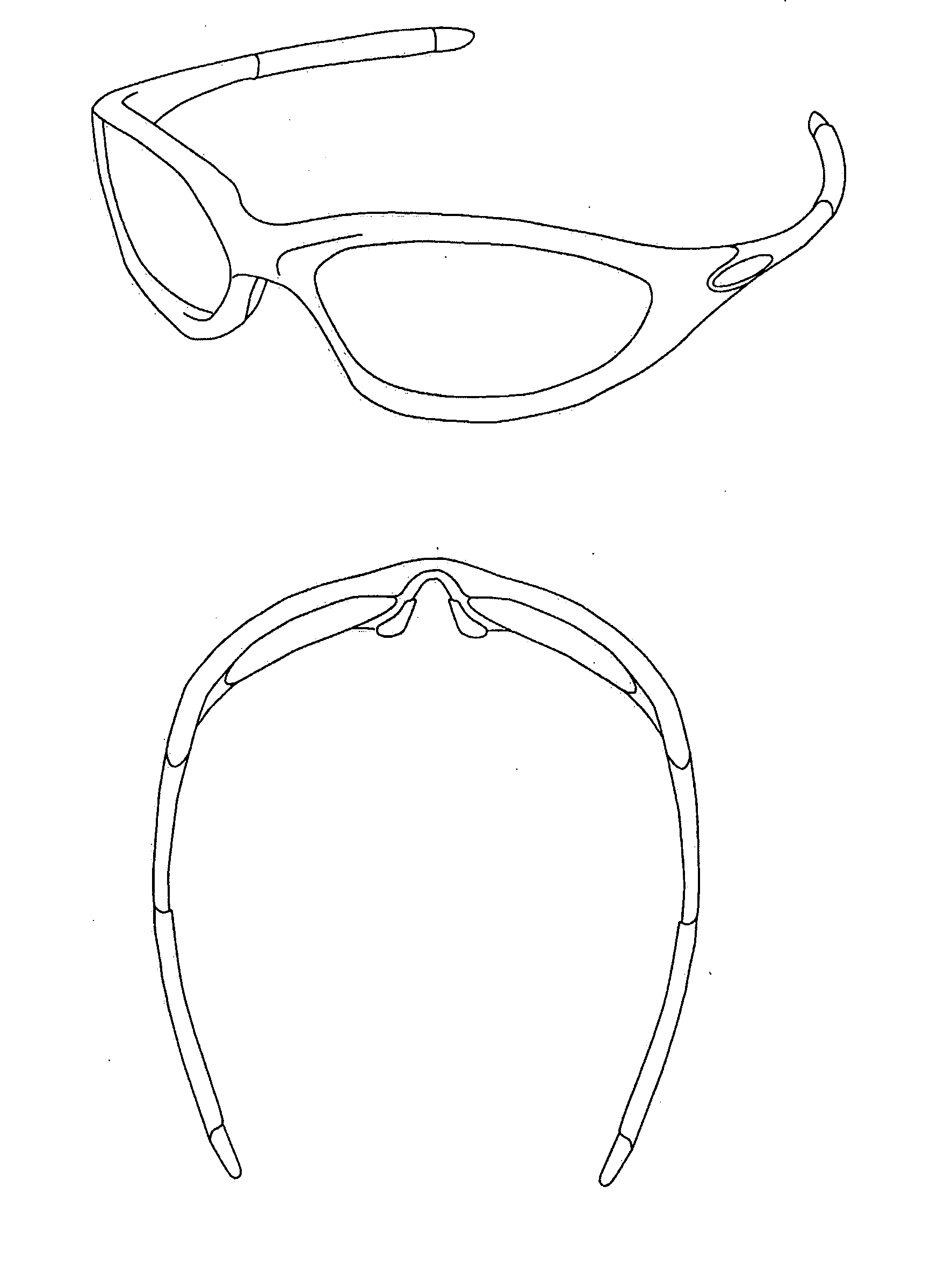
CROSS-REFERENCE TO RELATED APPLICATIONS [0001] This application claims priority from Japanese Patent Application No. 2006-201673, filed on Jul. 25, 2006 in the Japan Patent Office, the disclosure of which is incorporated herein by reference in its entirety. BACKGROUND OF THE INVENTION [0002] 1. Technical Field [0003] The present invention relates to a method for designing a spectacle lens mounted in a spectacle frame having a large bend angle, such as a wraparound-type spectacle frame, a spectacle lens, and a pair of spectacles mounted in a spectacle frame. [0004] 2. Description of the Related Art [0005] Currently, a wraparound-type spectacle frame, which is mainly used for sports glasses, has been increasingly used in activities other than sports. FIGS. 3A and 3B are perspective views of an example of a wraparound-type spectacle frame as viewed obliquely and from above, respectively. The wraparound-type spectacle frame illustrated in FIGS. 3A and 3B has a large bend angle, which is...

Claims


Application Information

Patent Timeline
IPC IPC(8): G02C7/02G02C5/00
CPCG02C7/02G02C7/027G02B3/00
Inventor KAMISHITA, KAORUITO, AYUMUKAGA, TADASHI
Owner HOYA LENS MFG PHILIPPINES
Learn More