
Flexible hardware password protection and access control

a hardware password protection and access control technology, applied in the field of optic modules, can solve the problems of unfavorable communication between the host and the module, unfavorable access control, and high cost of the module, and achieve the effect of preventing the module from being used in the wrong direction, and preventing the module from being used

Active Publication Date: 2008-01-24
MACOM TECH SOLUTIONS HLDG INC
View PDF27 Cites 13 Cited by
  • Summary
  • Abstract
  • Description
  • Claims
  • Application Information

AI Technical Summary

Benefits of technology

[0008]To overcome the drawbacks of the prior art, a method and apparatus for controlling access to data stored in a memory of an optic module is disclosed. In one embodiment of this method for controlling access to data stored in a first memory in an optic module is first provided. Then, responsive to providing a password entry to a memory controller, the system reads one or more access level passwords from the first memory or a second memory. This exemplary method of operation then compares the password entry to the one or more access level passwords and, responsive to the comparing not locating a match between the password entry and an access level password, the system denies access to the data stored in the first memory. Alternatively, responsive to the comparing locating a match between the password entry and an access level password, the system grants access to the data stored at the memory addresses defined in an address access range associated with the matched access level password.

Problems solved by technology

These modules are often expensive and relied upon for important data communication.
In all environments, module failure is undesirable and as such, optic modules are often configured with monitoring or diagnostic capability.
Although multiple optic modules may be located within a single enclosure or unit, one drawback to prior art system is that each optic module, if configured in accordance with the standard governing optic modules has the same address and share a common memory.
When multiple optic modules are located within a single enclosure or module, this limitation may undesirably hinder efficient communication between a host and with the modules.
One additional disadvantage of prior art modules is that the memory locations for an entire module may be access through use of a single password.
As such, it is not possible to limit or selectively control access to the numerous different memory locations in the module.
This is a drawback because it may be desired to restrict access to certain memory locations for certain individuals, while allowing greater access to other individuals or entities.

Method used


Image

  • Flexible hardware password protection and access control
  • Flexible hardware password protection and access control
  • Flexible hardware password protection and access control

Examples


Embodiment Construction

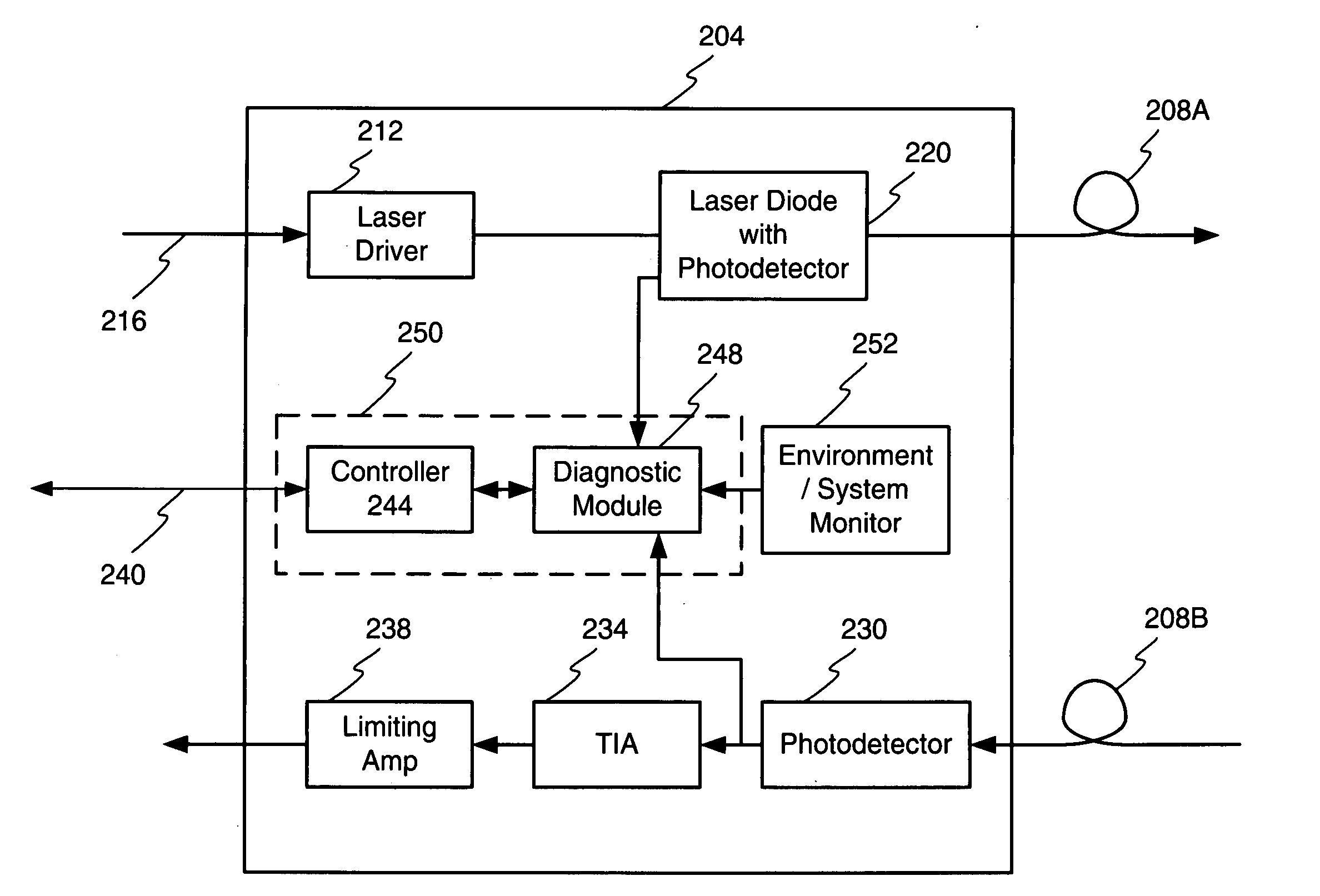
[0022]FIG. 1 illustrates a block diagram of an example environment of use for the method and apparatus disclosed herein. This example embodiment comprises an optic module 204 as may be configured to communicate over optic fiber 208A, 208B. In general, the module 204 may be considered for purposes of discussion as a transmitter, shown at the top of the figure within the module 204, and a receiver, shown at the bottom of the module. A control and monitoring system 250, 252 is shown generally between the transmitter and receiver and may be considered as shared between the transmitter and receiver portion of the module 204. Although not shown, additional processing, gating, buffering, or other elements may be associated with the module 204.

[0023]In this example embodiment the transmitter comprises a laser driver 212 configured to receive one or more incoming signals on one or more data inputs 216. The laser driver 212 converts an incoming voltage level, representing an outgoing data sig...


PUM


Abstract

An optic module is disclosed having a memory configured to store data. To selectively control access to the memory and data stored in memory, a method and apparatus for memory access control is provided which creates access levels. The access levels include associated passwords, and read / write capability control, and address access range. During use a technician or other party would enter a password via an interface and the entered password is compared to the password associated with each access level. If a match is not found, then access to the memory, a hence data within the memory is denied. If a match is found the technician gains access to the data stored in the memory address range associated with the access level. Read and write access may also be granted or denied.

Description

FIELD OF THE INVENTION[0001]The invention relates to optic modules, and in particular, to a memory access control in an optic module.RELATED ART[0002]Optic modules are utilized to perform communication over optic channels. These modules are often expensive and relied upon for important data communication. In other situations or in the future, optic modules may be utilized in consumer applications to increase bandwidth. In all environments, module failure is undesirable and as such, optic modules are often configured with monitoring or diagnostic capability. Such monitoring of one or more of the module outputs, inputs or other factors, such an environment, can predict or detect failure.[0003]To facilitate monitoring, the modules may be equipped with one or more monitoring elements and memory or other data storage elements. The modules may store system data, environment data, and threshold values. A processor and user interface maybe provided so that a user may access the data values ...

Claims


Application Information

Patent Timeline
Patent Type & Authority Applications(United States)
IPC IPC(8): H04L9/32
CPCG06F21/78
Inventor LE, MIKEJONES, KEITH R.SADA, GILBERTO I.
Owner MACOM TECH SOLUTIONS HLDG INC
Learn More