
Integrated Lancet and Blood Glucose Meter System

a glucose meter and integrated technology, applied in the field of analyte test sensors, can solve the problems of increasing the overall complexity and manual dexterity required to use such a system, piercing the skin of the patient, and the above-described glucose measurement procedure requires multiple preparatory steps, so as to achieve the effect of convenient use and low manufacturing cos

Inactive Publication Date: 2008-01-24
ABBOTT DIABETES CARE INC
View PDF80 Cites 145 Cited by
  • Summary
  • Abstract
  • Description
  • Claims
  • Application Information

AI Technical Summary

Benefits of technology

The present invention provides a novel sensor array that can be easily installed into a compatible analyte test monitor. The sensor array includes a plurality of interconnected analyte test sensors that conform to non-planar surfaces and are designed to be cost-effective and easy to use. The sensor array can be installed by hingeably coupling two test sensors or by using a unitary substrate with separate electrodes for each test sensor. The sensor array can also include interlocking or separate test sensors that are designed to improve the accuracy and reliability of the analyte test.

Problems solved by technology

Typically, the movement of the lancet from its retracted position to its extended position is effected with such force that contact of the moving lancet tip with the skin of a patient results in the piercing of the skin of the patient.
A principal drawback associated with blood glucose monitoring systems of the type described above is that the above-described glucose measurement procedure requires multiple preparatory steps prior to each assay.
As can be appreciated, the fact that the aforementioned process fails to provide the user with a continuous means for performing multiple assays significantly increases the overall complexity and manual dexterity which is required to use such a system, which is highly undesirable.
Although useful in performing multiple continuous glucose measurements, sensor arrays of the type described above suffer from a notable drawback.
Specifically, sensor arrays of the type described above are typically constructed with a limited degree of flexibility and / or bendability.
Due to their relative rigidity, the sensor arrays are only capable of movement along a single plane (e.g., either through rotation or linear displacement).
As a result, these types of sensor arrays often preclude design engineers from constructing a complementary meter of reduced size and / or mechanical complexity, which is highly undesirable.

Method used


Image

  • Integrated Lancet and Blood Glucose Meter System
  • Integrated Lancet and Blood Glucose Meter System
  • Integrated Lancet and Blood Glucose Meter System

Examples


first embodiment

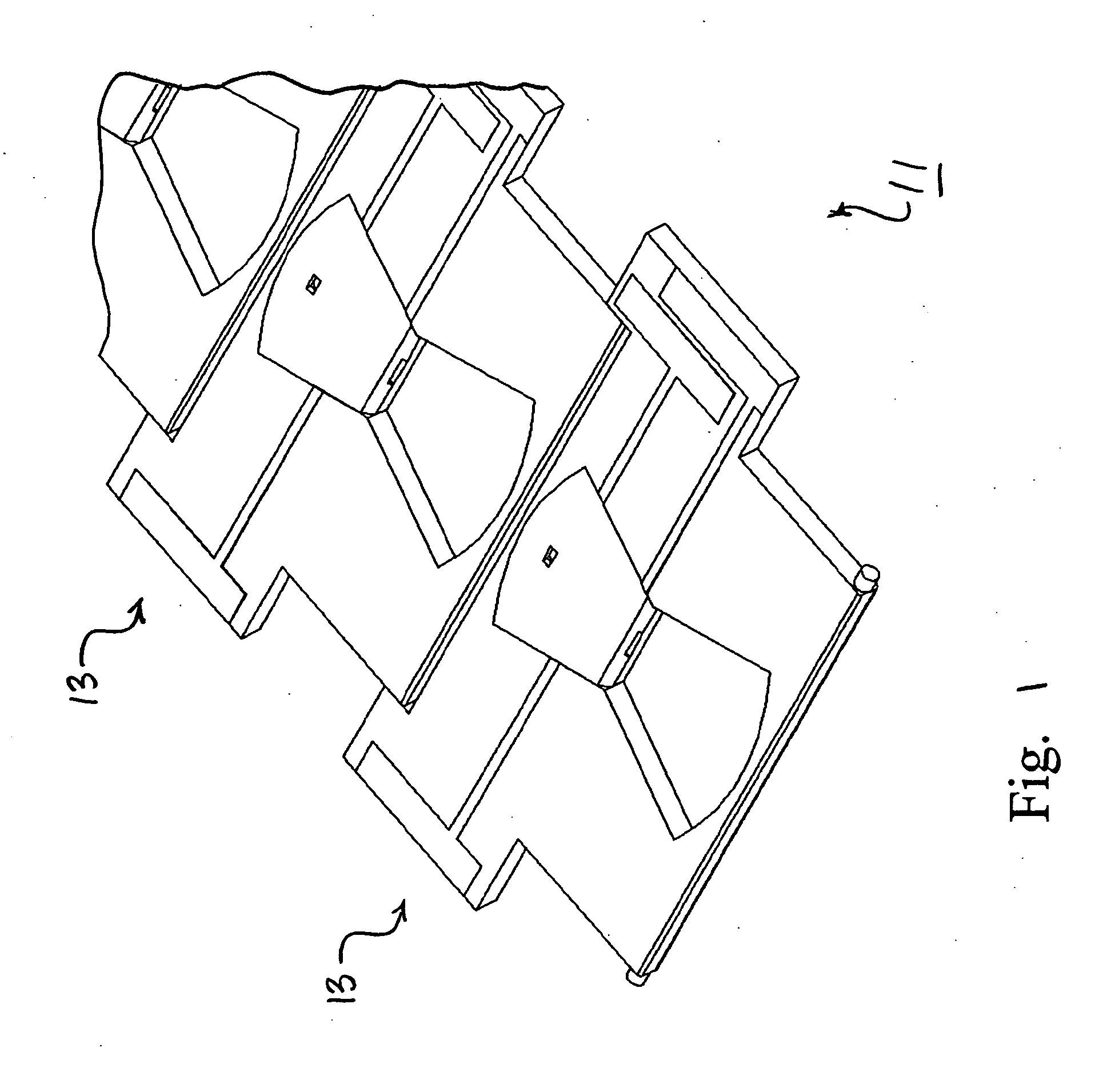
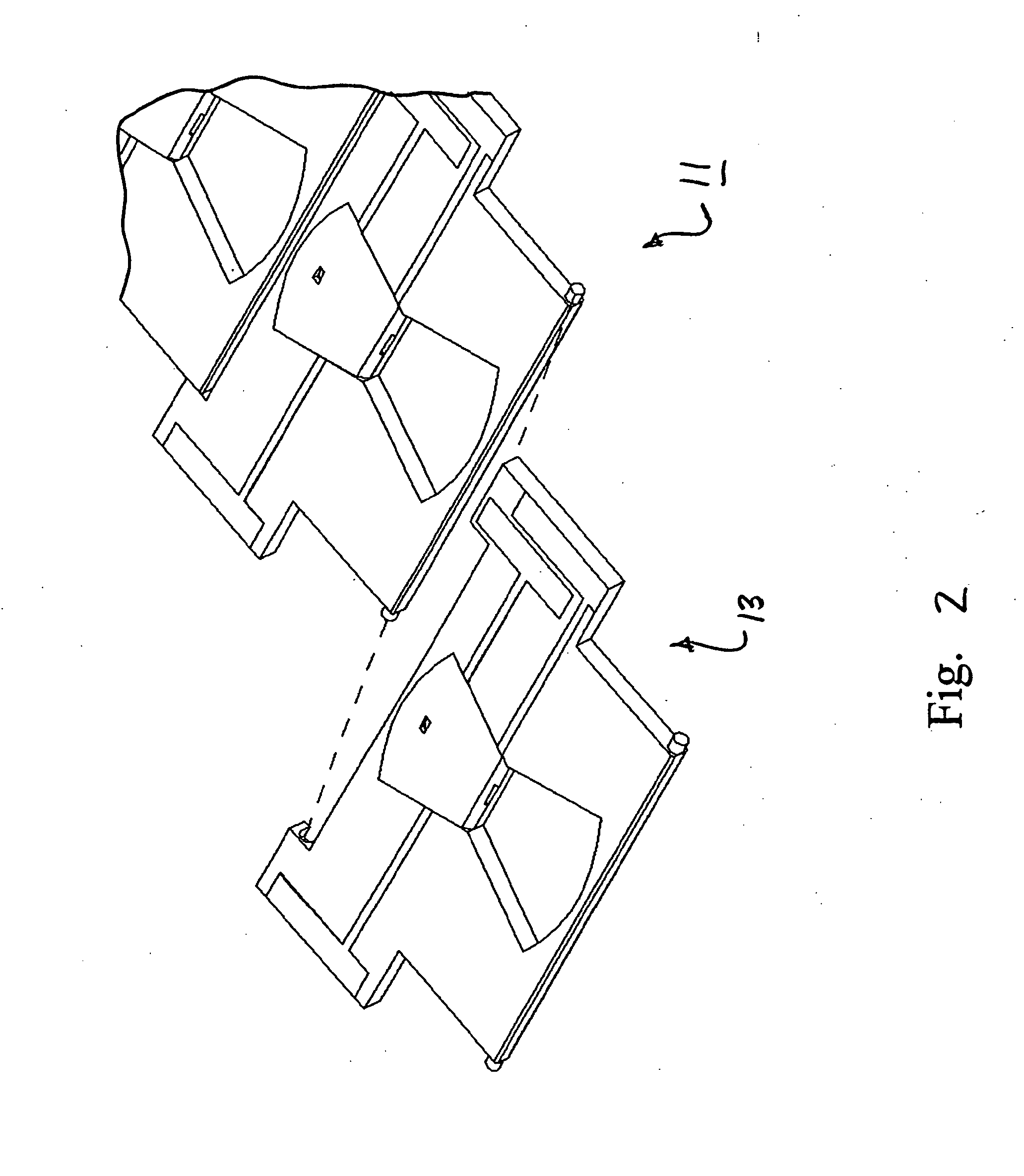
[0047] Referring now to the drawings, there is shown in FIGS. 1-2 a sensor array constructed according to the teachings of the present invention, the sensor array being identified generally by reference numeral 11. As will be described further in detail below, sensor array 11 is designed to be continuously fed into a compatible analyte test monitor. In this manner, a plurality of blood tests can be performed without requiring the user to unwrap and load individual test strips into the test monitor, which is a principal object of the present invention.

[0048] Sensor array 11 includes a plurality of individual analyte test sensors 13 which are hingedly interconnected in a front-to-back arrangement. In this manner, sensor array 11 can be configured to conform to a non-planar surface, as will be described further in detail below.

[0049] Referring now to FIGS. 3-5, each analyte test sensor 13 includes a unitary, non-conductive substrate 15 which is preferably constructed of plastic using ...

second embodiment

[0078] Referring now to FIGS. 9(a) and 9(b), there is shown a sensor array which is constructed according to the teachings of the present invention, the sensor array being identified generally by reference numeral 111. Sensor array 111 is similar to sensor array 11 in that sensor array 111 includes a plurality of test sensors 113 which are arranged in a front-to-back arrangement. However, sensor array 111 differs from sensor array 11 in the manner in which test sensors 113 are interconnected.

[0079] Specifically, sensor array 111 includes a one-piece, non-conductive substrate 115 which is common to each of the test sensors 113. Substrate 115, which is preferably constructed of plastic using conventional molding techniques, includes a substantially flat top surface 117 and a bottom surface 119.

[0080] Substrate 115 is scored at multiple locations to enable sensor array 111 to bend. As seen most clearly in FIG. 9(b), a plurality of laterally extending lines of weakness 121 are formed i...

third embodiment

[0085] Referring now to FIGS. 10 and 11, there is shown a sensor array which is constructed according to the teachings of the present invention, the sensor array being identified generally by reference numeral 211. Sensor array 211 includes a plurality of individual test sensors 213 which are spaced apart from one another and are configured in a parallel, front-to-back arrangement.

[0086] Each test sensor 213 includes a unitary, non-conductive substrate 215 which is preferably constructed of plastic using conventional molding techniques. Substrate 215 is preferably in the form of a thin, rectangular strip which includes a substantially flat top surface 217, a substantially flat bottom surface 219, a front edge 221, a back edge 223, and a pair of side edges 225. However, it is to be understood that the particular shape of substrate 215 could be modified without departing from the spirit of the present invention.

[0087] A pair of carbon-layer electrodes 227-1 and 227-2 are deposited on...


PUM

PropertyMeasurementUnit
electrical energyaaaaaaaaaa
reactive areaaaaaaaaaaa
electrical poweraaaaaaaaaa

Abstract

A sensor array designed to be continuously indexed through a compatible blood glucose test monitor for the purpose of conducting multiple consecutive blood glucose measurements. The sensor array can be configured to substantially conform to a non-planar surface. In one embodiment, the sensor array includes first and second test sensors which are hingedly coupled together through a pin and socket interconnection. In another embodiment, the sensor array includes a unitary, non-conductive substrate which is scored to define one or more fold lines, a first set electrodes deposited on the substrate to define a first test sensor, and a second set of electrodes deposited on the substrate to define a second test sensor. In another embodiment, the sensor array includes a first test sensor, a second test sensor spaced apart from said first test sensor, a first spacer mounted on the first test sensor, a second spacer mounted on the second test sensor, and a unitary flexible member disposed across said first and second spacers.

Description

PRIORITY [0001] This application is a continuation of U.S. patent application Ser. No. 10 / 899,773, filed Jul. 27, 2004, and is hereby incorporated by reference.BACKGROUND OF THE INVENTION [0002] The present invention relates generally to analyte test sensors and more particularly to a novel array of analyte test sensors. [0003] There are many medical conditions which require frequent measurement of the concentration of a particular analyte in the blood of a patient. For example, diabetes is a disease which typically requires a patient to routinely measure the concentration of glucose in his / her blood. Based upon the results of each blood glucose measurement, the patient may then require a particular drug treatment (e.g., an injection of insulin) in order to regulate that the blood glucose level of the patient remains within a specified range. Exceeding the upper limit of said range (hyperglycemia) or dropping beneath the lower limit of said range (hypoglycemia) should be avoided wit...

Claims


Application Information

Patent Timeline
Patent Type & Authority Applications(United States)
IPC IPC(8): A61B5/00A61B17/32C12Q1/54
CPCA61B5/1411G01N33/4875A61B2562/0295A61B5/1486A61B5/150022A61B5/150099A61B5/150213A61B5/150358A61B5/150412A61B5/150503A61B5/15113A61B5/1519A61B5/15194A61B5/157
Inventor ZOCCHI, MICHAEL R.
Owner ABBOTT DIABETES CARE INC
Learn More