
Information Processing Apparatus and Information Processing Method, Recording Medium, and Program

Inactive Publication Date: 2008-01-24
SONY CORP
View PDF18 Cites 11 Cited by
  • Summary
  • Abstract
  • Description
  • Claims
  • Application Information

AI Technical Summary

Benefits of technology

[0048] According to the first aspect of the present invention, compression encoded data can be edited, and particularly since the range for re-encoding can be extended based on a generation code amount provided to the reference encoding range, deterioration of the image in the proximity of the editing point can be prevented without allowing the buffer to fail.
[0049] According to the second aspect of the present invention, compression coded data can be spliced and re-encoded, and particularly since the range for re-encoding can be extended based on a generation code amount provided to the reference encoding range, deterioration of the image in the proximity of the editing point can be prevented without allowing the buffer to fail.

Problems solved by technology

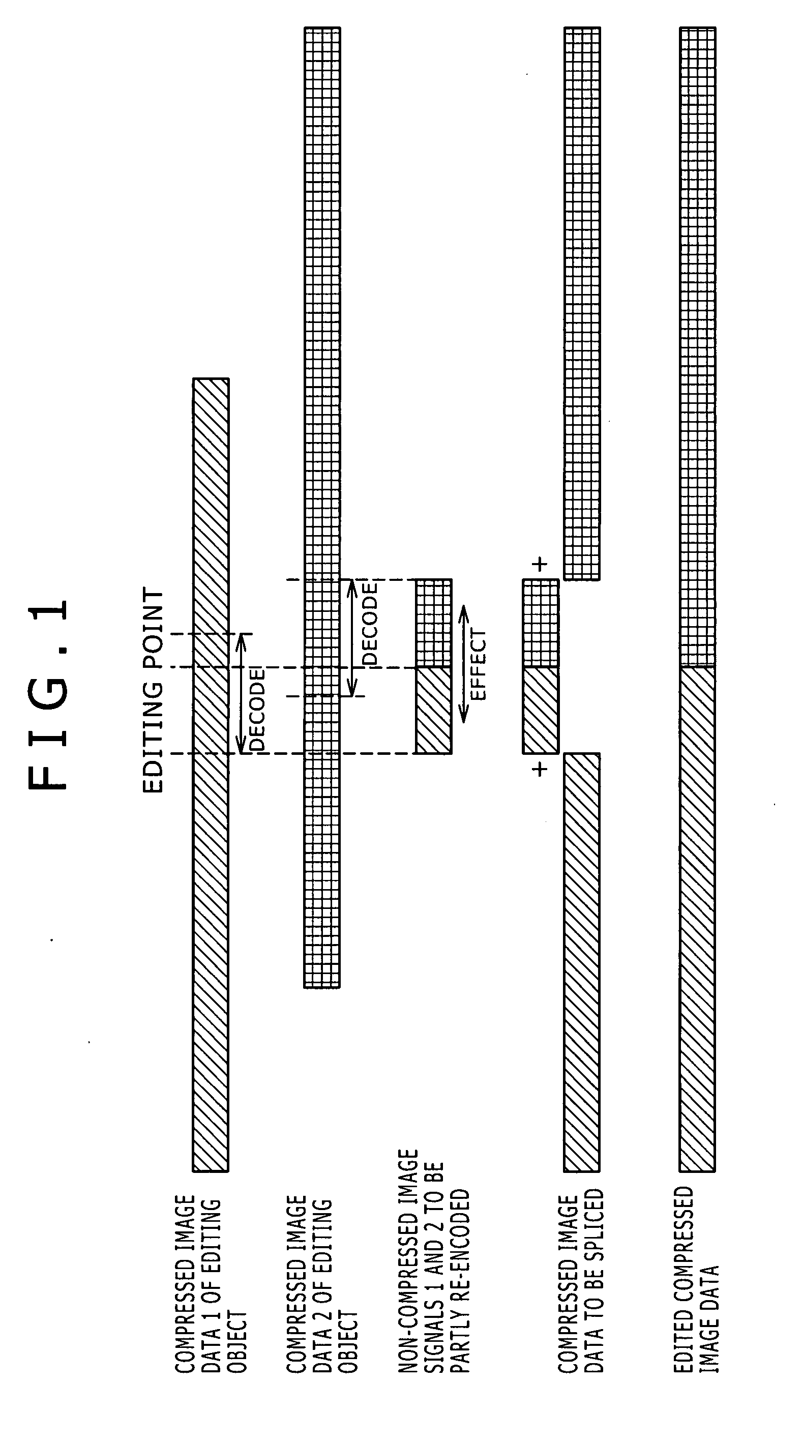
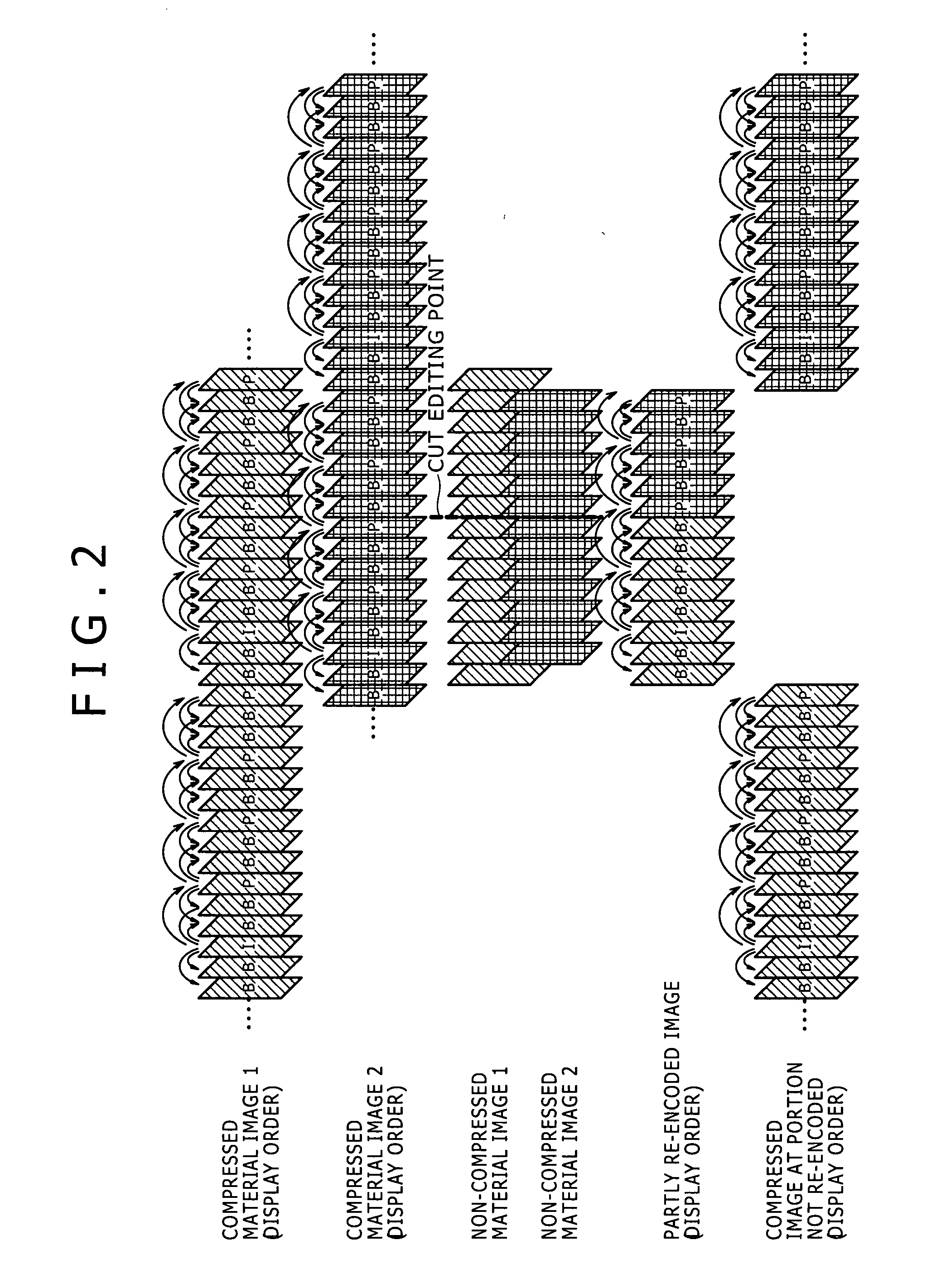
However, where it is intended to edit images, since compressed image materials formed using interframe prediction cannot be spliced together while they remain in the form of a compressed image signal because they have a relationship of compressed signals by prediction between frames.
However, where an image signal of a high definition having a large information amount is handled like, for example, a high definition (HD) signal, if only interframe compression is used for encoding, then only a low compression efficiency is obtained.
Therefore, in order to transmit or store a large amount of data, an expensive system is required in that a high transfer speed is required, a large storage capacity is required or a high processing speed is required.
However, if the GOP is excessively long, then the editing control in the frame accuracy becomes difficult, and a problem in operation takes place in editing in business applications.
However, if such a method as described above with reference to FIG. 1 is used to perform editing and re-encoding, then this gives rise to a problem that a picture cannot be referred to at a joint between a portion for which re-encoding is performed and another portion for which no re-encoding is performed.

Method used


Image

  • Information Processing Apparatus and Information Processing Method, Recording Medium, and Program
  • Information Processing Apparatus and Information Processing Method, Recording Medium, and Program
  • Information Processing Apparatus and Information Processing Method, Recording Medium, and Program

Examples


first embodiment

[0099] Now, operation of the editing apparatus 1 is described.

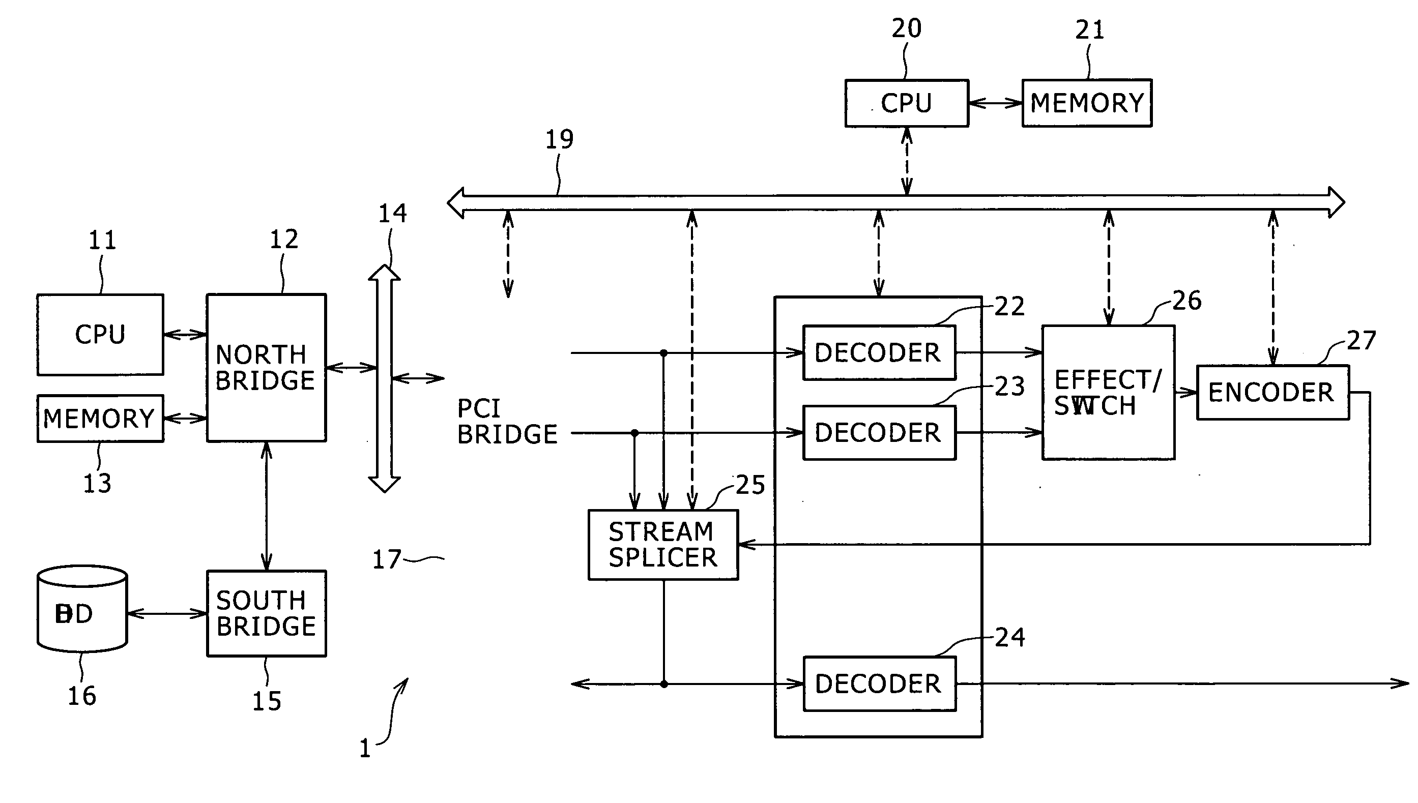
[0100] In the HDD 16, data of a compressed material image 1 and a compressed material image 2 compressed in accordance with the Long Open GOP system illustrated in FIG. 5 are stored. Referring to FIG. 5, the compressed material image 1 and the compressed material image 2 are illustrated in an order of pictures to be displayed (in a display order).

[0101] The CPU 11 controls the south bridge 15 to read out the data of the compression coded compressed material image1 and the data of the compression coded compressed material image 2 from the HDD 16 in response to an operation of a user supplied thereto from an operation inputting section not shown and supply the read out data to the memory 18 through the north bridge 12, PCI bus 14 and PCI bridge 17 so as to be stored into the memory 18. Further, the CPU 11 supplies information representing editing points and a command indicating starting of editing to the CPU 20 through th...

second embodiment

[0130] Operation of the editing apparatus 1 is described.

[0131] The CPU 11 controls the south bridge 15 to read out the data of the compression coded compressed material image 1 and the data of the compression coded compressed material image 2 from the HDD 16 in response to an operation of a user supplied thereto from an operation inputting section not shown and supply the read out data to the memory 18 through the north bridge 12, PCI bus 14 and PCI bridge 17 so as to be stored into the memory 18. Further, the CPU 11 supplies information representing editing points and a command indicating starting of editing to the CPU 20 through the north bridge 12, PCI bus 14, PCI bridge 17 and control bus 19.

[0132] The CPU 20 determines, based on the information representative of the editing points supplied thereto from the CPU 11, those ranges of the compression coded data of the compressed material image 1 and the compression coded data of the compressed material image 2 within which re-enc...

third embodiment

[0165] A third embodiment wherein control is performed so that a re-encoding range is extended and the generation code amount in the encoding process by the encoder 27 is increased in the proximity of an editing point is described below.

[0166] First, a minimum re-encoding interval including an editing point as in the case described hereinabove with reference to FIG. 11 is considered. An effect interval including an editing point is hereinafter referred to as editing duration.

[0167] In order to maintain the continuity of the VBV Occupancies at a start point and an end point of re-encoding, encoding by the encoder 27 is controlled by the CPU 20 so that the VBV Occupancies at the start point and the end point of the encoding may coincide with each other.

[0168] Since the generation code amount of an I picture is usually greater than that of a P picture or a B picture, the occupancy is low at the top of a GOP and increases in a rear half of the GOP. Where the code amount allocation is ...


PUM


Abstract

An information processing apparatus and method for splicing first compressed image data with second compressed image data. The method includes performing a decoding process for a first decoding interval that includes a first editing point set to the first compressed image data to produce a first non-compressed image signal. A second decoding process includes a second editing point set to the second compressed image data to produce a second non-compressed image signal. A re-encoding process re-encodes an interval of a third non-compressed image signal and the first and second non-compressed image signals are spliced at the first and second editing points to produce third compressed image data.

Description

TECHNICAL FIELD [0001] This invention relates to an information processing apparatus and an information processing method, a recording medium, and a program, and more particularly to an information processing apparatus and an information processing method, a recording medium, and a program suitable for use where video data compressed bidirectional interframe prediction are edited. BACKGROUND [0002] Image compression methods represented by an MPEG (Moving Picture Coding Experts Group / Moving Picture Experts Group) method achieve a high compression efficiency by compression encoding an image signal using interframe prediction. However, where it is intended to edit images, since compressed image materials formed using interframe prediction cannot be spliced together while they remain in the form of a compressed image signal because they have a relationship of compressed signals by prediction between frames. Therefore, a system which is configured taking it into consideration in advance ...

Claims


Application Information

Patent Timeline
IPC IPC(8): H04N7/12H04N5/91H04N7/24H04N19/00H04N19/114H04N19/115H04N19/126H04N19/134H04N19/136H04N19/137H04N19/14H04N19/15H04N19/152H04N19/159H04N19/172H04N19/196H04N19/40H04N19/48H04N19/503H04N19/573H04N19/61H04N19/625H04N19/91
CPCH04N21/23406H04N21/23424H04N21/44004H04N19/194H04N21/854H04N19/15H04N21/44016H04N19/152H04N5/92
Inventor FUCHIE, TAKAAKIKOYABU, KYOHEIYOSHINARI, HIROMI
Owner SONY CORP
Learn More