
Adaptive data acquisition for an imaging system

a data acquisition circuit and imaging system technology, applied in transmission systems, analogue/digital conversion, instruments, etc., can solve the problems of reducing the amplitude of the shaped pulse, and reducing the energy resolution of the circui

Active Publication Date: 2008-01-24
GENERAL ELECTRIC CO
View PDF15 Cites 21 Cited by
  • Summary
  • Abstract
  • Description
  • Claims
  • Application Information

AI Technical Summary

Problems solved by technology

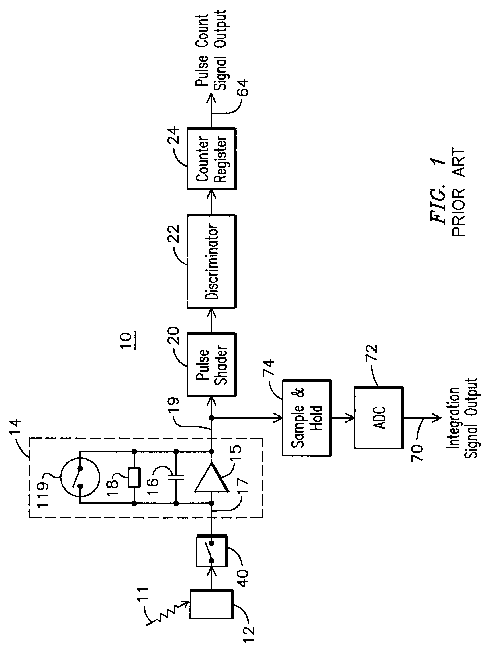
However, a low resistance resistor 18 may result in decreased energy resolution due in part to the known phenomenon of ballistic deficit.
Variability in a charge pulse amplitude results in a decreased energy resolution of the circuit.
However, if the shaping time is made too long, this may result in excessive circuit dead time that can lead to overlap of shaped pulses and a distortion in the amplitude of the shaped pulse.

Method used


Image

  • Adaptive data acquisition for an imaging system
  • Adaptive data acquisition for an imaging system
  • Adaptive data acquisition for an imaging system

Examples


Embodiment Construction

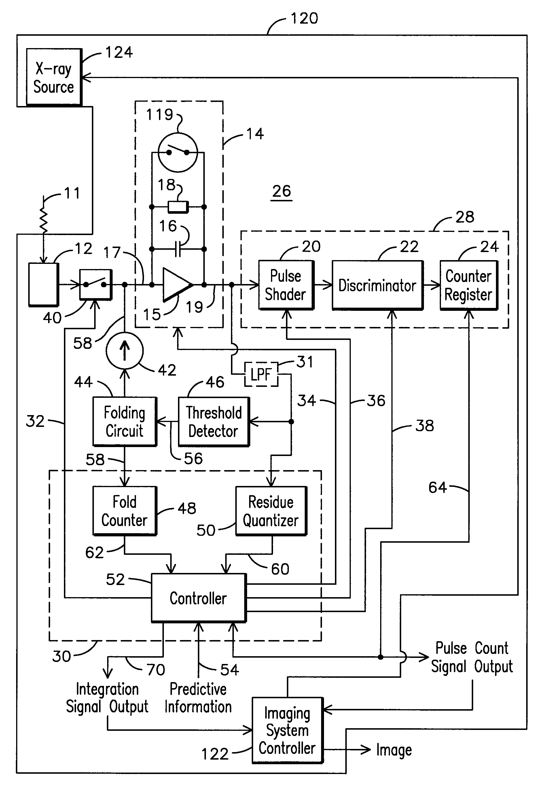
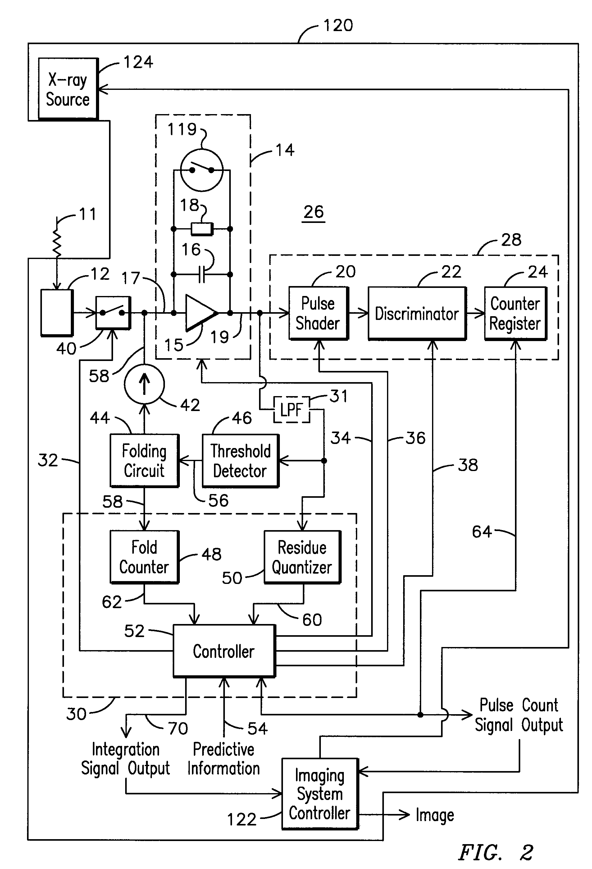
[0010]In data acquisition circuits of imaging systems such as CT systems, there is a need to achieve a desired energy resolution over a wide range of energy detection conditions. For example, a conventional photon counting data acquisition circuit of a CT system needs to be able to provide sufficient energy resolution at both relatively low count rates and at relatively high count rates. The inventors have innovatively realized that by dynamically modifying operating parameters of a imaging data acquisition circuit, a desired energy resolution may be achieved over a broad range of photon counting rates. In particular, by controlling an operating parameter of the imaging data acquisition circuit responsive to a pulse parameter indicative of the pulse rate and integrated charge, a desired energy resolution for varying count rate conditions may be achieved.

[0011]FIG. 2 is a schematic diagram of an example embodiment of an adaptive data acquisition circuit 26 for use in an imaging syste...


PUM


Abstract

An adaptive data acquisition circuit (26) includes an amplifier (14) for amplifying electrical pulses generated by a detector (12) responsive to energy incident at the detector. The adaptive data acquisition circuit also includes a counting circuit (28) for counting amplified electrical pulses generated by the amplifier. In addition, the adaptive data acquisition circuit includes a digital logic circuit (30) for determining a pulse parameter indicative of a pulse rate and an amount of energy present in the amplified electrical pulses and for generating a control signal (34) responsive to the pulse parameter for controlling an operating parameter of the data acquisition circuit.

Description

FIELD OF THE INVENTION[0001]The present invention relates to imaging systems, and, more particularly, to an adaptive data acquisition circuit for an imaging system.BACKGROUND OF THE INVENTION[0002]FIG. 1 illustrates a conventional data acquisition circuit 10 for use in imaging systems, for example, computer tomography (CT) systems, to count energy quanta received from a target being imaged. Such circuits 10 typically include a detector 12 generating current charge pulses responsive to received energy 11, such as x-ray photons incident on the detector 12. The output from such a system may include pulse counts 64. An amplifier 14, such as an integrating trans-impedance amplifier, typically comprising an operational amplifier (op amp) 15 with an integrating capacitor 16, resistor element 18, and low impedance switch 119 connected in feedback between an inverting terminal and an output terminal of the op amp 15, converts the current charge pulses into voltage pulses. Optionally, paralle...

Claims


Application Information

Patent Timeline
IPC IPC(8): H03M7/34
CPCG01T1/17
Inventor ASTLEY, OLIVER RICHARDTKACZYK, JOHN ERICRAO, NARESH KESAVANLEBLANC, JAMES WALTERLI, WENDU, YANFENG
Owner GENERAL ELECTRIC CO
Learn More