
Portable cyclonic dust collection system

Inactive Publication Date: 2008-01-24
WITTER ROBERT M
View PDF7 Cites 43 Cited by
  • Summary
  • Abstract
  • Description
  • Claims
  • Application Information

AI Technical Summary

Benefits of technology

[0008]Accordingly, it is an object of this invention to provide an efficient portable dust collection arrangement that avoids the drawbacks of the prior art.

Problems solved by technology

The same problem of environmental dust arises in metal working and ceramics also.
The upper filter tends to blind or clog after a limited operation time, which reduces the efficiency of the unit.
Consequently, for a woodworking machine that generates more dust than these machines, the air flow would not be sufficient to capture all the dust produced.
However, it is not a simple matter to produce a bigger or more powerful dust collection unit of that design.
In practice, no one has attempted to use a true cyclonic separator as a dust separation and collection device between the dust producing tool and the portion of the unit where the air is filtered and returned to the ambient.
Further, the current equipment designs do not have any means for removing or loosening the collected dust particles from the filter, except to remove the filter and blast it with compressed air.

Method used


Image

  • Portable cyclonic dust collection system
  • Portable cyclonic dust collection system
  • Portable cyclonic dust collection system

Examples


Embodiment Construction

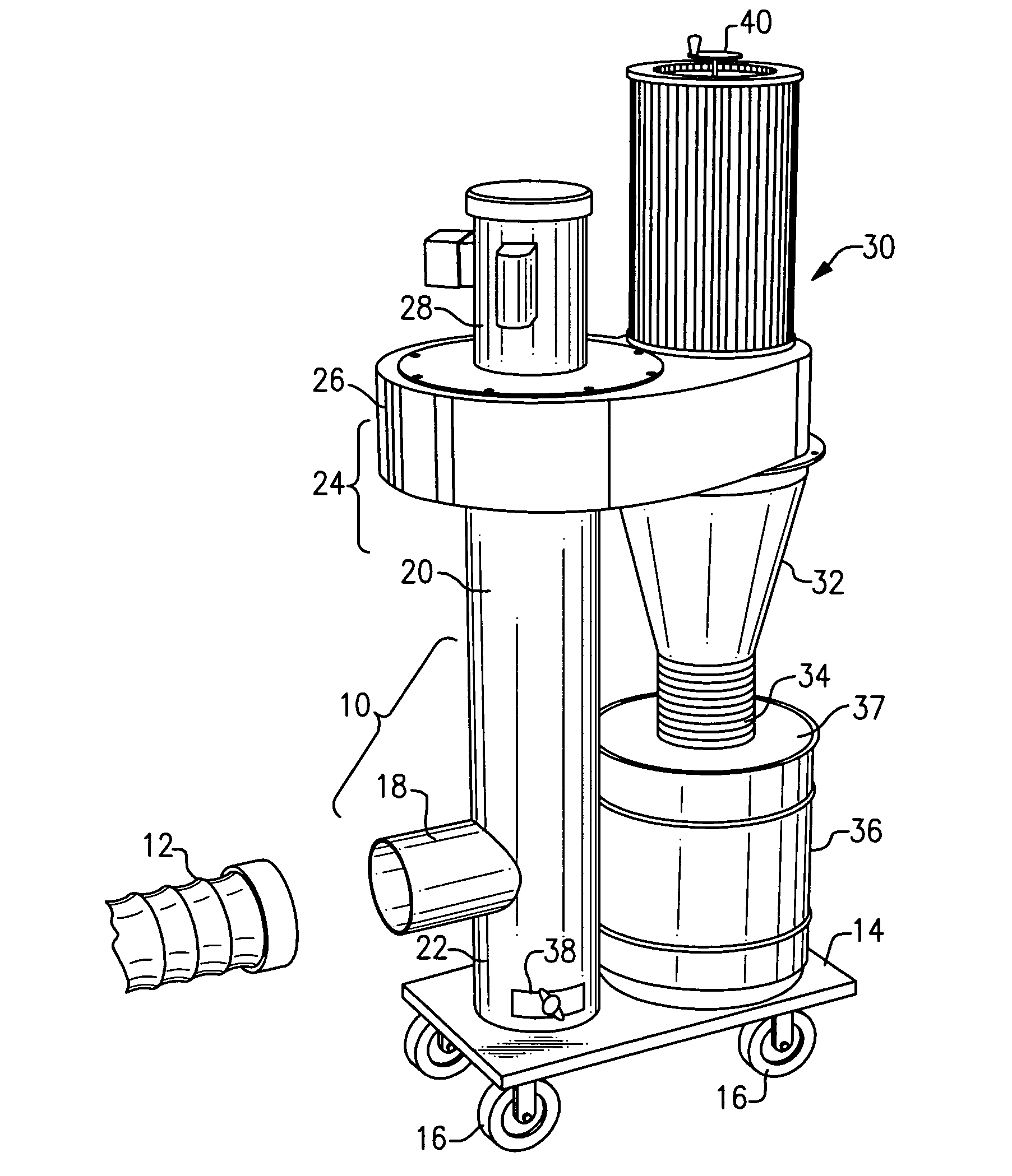
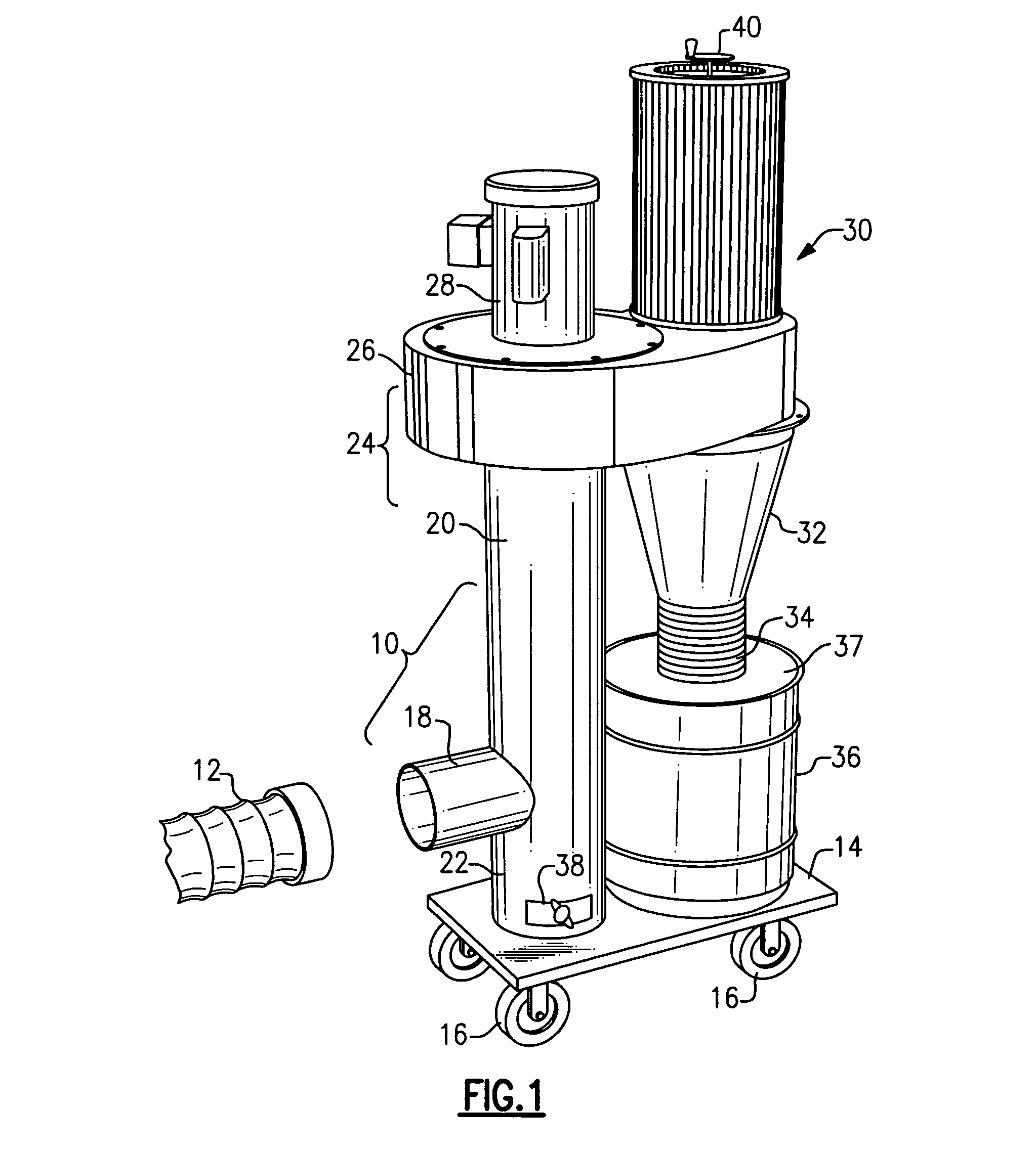
[0031]Now with reference to the Drawing, FIG. 1 shows a woodshop application, in which a portable dust separation and collection device 10, according to an embodiment of the present invention, is coupled to a flexible duct or hose 12 to receive an airflow containing entrained wood process dust from a saw, sander, or other woodworking machine (not shown).

[0032]As illustrated here, the device 10 has a platform or base 14 with rollers, casters, or wheels 16, that permit the device to be rolled to a convenient location within the shop. An inlet pipe 18, which is coupled by a quick-disconnect coupling 21 to the intake hose 12, leads to a vertical intake pipe 20 that is mounted at its lower end onto the base 14. This forms a trap 22 for large particles or chunks, which settle at the base end of the pipe 20, out of the air stream. The inlet pipe 18 enters the vertical intake pipe 20 several inches above its lower end to define the trap 22.

[0033]At the upper end of the pipe 20 there is a he...


PUM

PropertyMeasurementUnit
Flow rateaaaaaaaaaa
Flexibilityaaaaaaaaaa

Abstract

A portable dust collection system for a wood shop or other dust producing environment is employed with a sander, power saw, router or other dust-producing tool such as a woodworking tool. A movable platform has a vertical intake pipe supporting a head portion formed with a shroud. A centrifugal impeller drives the intake air stream plus any entrained particles into one or more cyclonic separators, which deposit the dust in a respective drum supported on the platform beneath the cyclone. The air inlet from the tool enters the vertical pipe at a point partway up the pipe, so that large particles drop to the bottom end of the pipe, where a clean-out door is provided. The exhaust or discharge air from the cyclonic separator(s) passes out through a filter cartridge to the ambient. A deflector plate prevents the dust from eddying back into the separator.

Description

BACKGROUND OF THE INVENTION[0001]This invention is directed to devices and equipment for collecting bulk solids, for example, process dust coming from a dust generating tool, such as a sanding machine, saw, router, planer or the like, where the dust is entrained in a flow of air from the source machine, and is separated out at the dust collection equipment, which precipitates the dust precipitates into a bag, drum, barrel, or other container. The invention is more specifically directed to a compact and efficient device to be used to separate and collect the dust from the airstream emerging from the tool, and to clean and filter the air stream which is then returned to the ambient. The invention is likewise concerned with a simple and straightforward portable dust separation assembly that can be associated with a tool that has a duct from which the air stream plus the entrained dust particles proceed.[0002]For many types of machines for processing a workpiece, some mechanism has to b...

Claims


Application Information

Patent Timeline
IPC IPC(8): B01D50/00
CPCB01D45/12B01D50/002B01D46/521B01D46/0075Y10S55/03B01D46/76B01D50/20
Inventor WITTER, ROBERT M.
Owner WITTER ROBERT M
Learn More