Traveling safety device for vehicle

a safety device and vehicle technology, applied in the direction of braking system, pedestrian/occupant safety arrangement, instruments, etc., can solve the problem of driver falling a sense of discomfor

Inactive Publication Date: 2008-01-17
HONDA MOTOR CO LTD
View PDF3 Cites 10 Cited by
  • Summary
  • Abstract
  • Description
  • Claims
  • Application Information

AI Technical Summary

Benefits of technology

[0012]According to this traveling safety device for a vehicle, when a driver has changed a brake operation after start of brake assist control, the brake assist pressure changes in proportion to the driver's brake operation. Thus, the driver's intention of increasing or reducing brake pressure is reflected in the brake assist, and it becomes easy for the driver to make a speed adjustment.
[0014]In this case, the brake assist pressure according to an increase or reduction in master cylinder pressure is calculated based on the ratio between the pressure of the master cylinder and the brake assist pressure after a predetermined time from the start of brake assist control. Thus, a driver can be prevented from feeling a sense of discomfort to a change in brake assist pressure.
[0016]In this case, the brake assist pressure according to an increase or reduction in master cylinder pressure is calculated based on the ratio between the pressure of the master cylinder and the brake assist pressure at the time of holding of a brake operation. Thus, a driver can be prevented from feeling a sense of discomfort to a change in brake assist pressure.
[0018]In this case, the brake assist pressure according to an increase or reduction in master cylinder pressure is calculated based on the ratio between the pressure of the master cylinder and the pressure of the brake wheel cylinder after a predetermined time from the start of brake assist control. Thus, a driver can be prevented from feeling a sense of discomfort to a change in brake assist pressure.
[0020]In this case, the brake assist pressure according to an increase or reduction in master cylinder pressure is calculated based on the ratio between the pressure of the master cylinder and the pressure of the brake wheel cylinder at the time of holding of a brake operation. Thus, a driver can be prevented from feeling a sense of discomfort to a change in brake assist pressure.

Problems solved by technology

However, if the brake assist pressure that has been set once is maintained till completion of the brake assist control, the driver will fell a sense of discomfort when the driver tries to change the stepping force of the brake pedal to make a speed adjustment, after the setting of the brake assist pressure.

Method used


Image

  • Traveling safety device for vehicle
  • Traveling safety device for vehicle
  • Traveling safety device for vehicle

Examples


Embodiment Construction

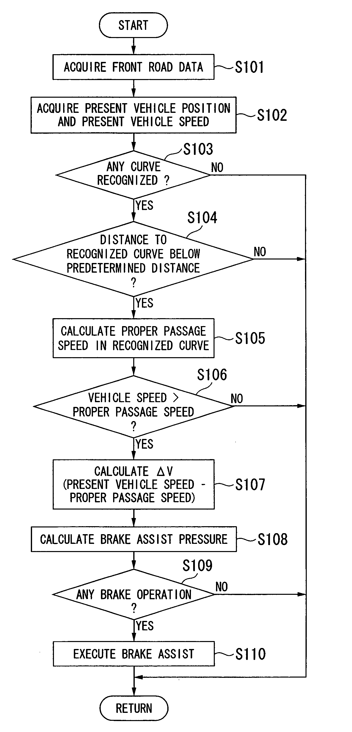
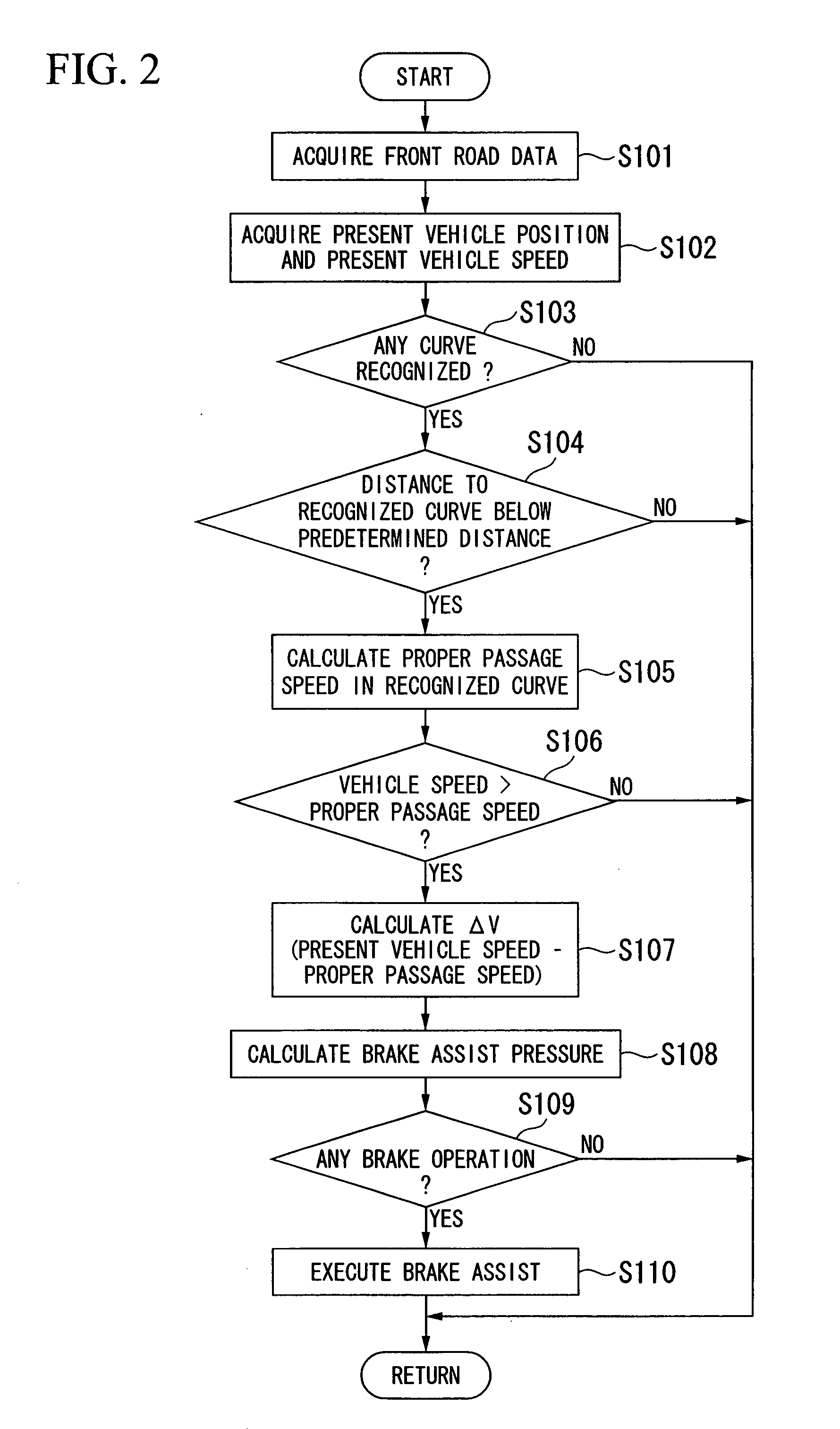
[0026]Hereinafter, one embodiment of a traveling safety device for a vehicle according to the present invention will be described with reference to FIGS. 1 to 5.

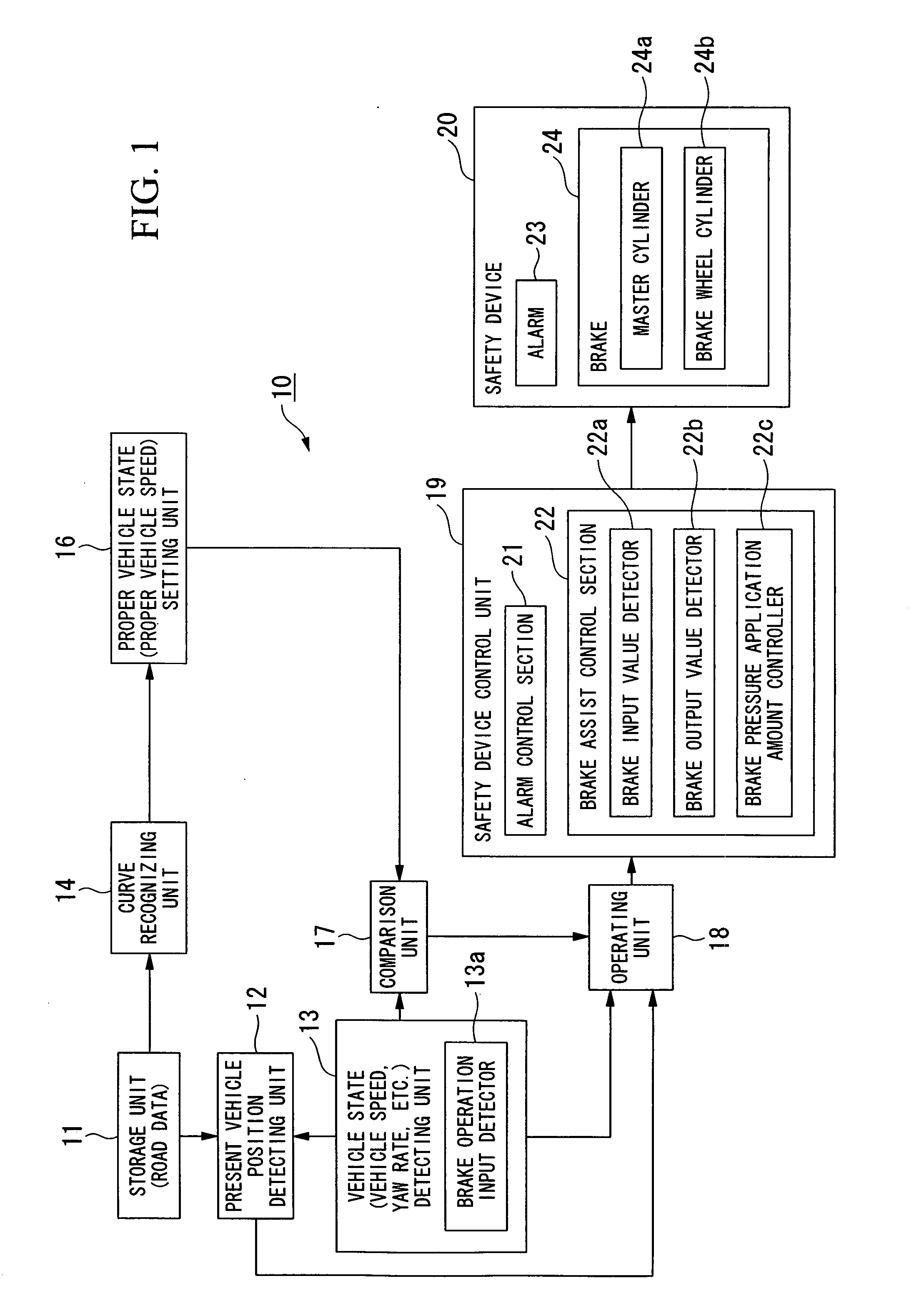
[0027]As shown in FIG. 1, a traveling safety device 10 for a vehicle in the present embodiment includes, for example, a storage unit (storage device) 11, a present vehicle position detecting unit (present vehicle position detecting device) 12, a vehicle state detecting unit (vehicle state detecting device) 13, a curve recognizing unit (curve recognizing device, road shape recognizing device) 14, a proper vehicle state setting unit (proper vehicle state setting device) 16, a comparison unit (comparing device) 17, an operating unit (operating device) 18, a safety device control unit 19, and a safety device 20.

[0028]The storage unit 11 stores node information and curve information related to a road as road data. The node information is, for example, data of coordinate points for grasping a road shape. The curve information is c...


PUM


Abstract

A traveling safety device for a vehicle of the present invention includes a brake device, a brake operation detecting device, a storage device, a present vehicle position detecting device, a vehicle state detecting device, a road shape recognizing device, a proper vehicle state setting device, a comparing device, a brake assist control device, a brake assist control device. The brake assist control device calculates an initial brake assist pressure based on a comparison result of the comparing device, and changes a brake assist pressure in proportion to the brake operation of the driver when a change in the brake operation by the driver has been detected after start of brake assist control based on the initial brake assist pressure.

Description

BACKGROUND OF THE INVENTION[0001]Priority is claimed on Japanese Patent Application No. 2006-194446, filed Jul. 14, 2006, and the contents of that are incorporated herein by reference.[0002]1. Field of the Invention[0003]The present invention relates to a traveling safety device for a vehicle, and specifically, to a traveling safety device for a vehicle provided with a brake assist system that assists in decelerating the vehicle if a driver has the intention of decelerating the vehicle.[0004]2. Description of the Related Art[0005]Conventionally, a system (hereinafter referred to as “collision prevention brake assist system”) that assists in decelerating a vehicle for prevention of a collision is known. In this collision prevention brake assist system, its greatest object is to reduce the braking time by a driver's brake operation to shorten the stopping distance of the vehicle. Therefore, a brake assist pressure is determined at an early stage of a brake operation (at an early stage...

Claims


Application Information

Patent Timeline
Patent Type & Authority Applications(United States)
IPC IPC(8): G01C21/26B60R21/00
CPCB60T7/22G08G1/16G01C21/26B60W50/14
Inventor SEKINE, HIROSHISUGIMOTO, YOICHIHIRATSUKA, HIDEKIKANAMORI, RYOHEI
Owner HONDA MOTOR CO LTD
Why Eureka
Try Eureka