Continuous material flow collecting and conveying device based on special-shaped screw rods

A conveying device and special-shaped screw technology, which is applied in the field of material packaging and conveying equipment, can solve the problems of reduced production efficiency, slow work rhythm, and high cost, and achieve the effects of convenient assembly and adjustment, convenient speed adjustment, and reliable performance

Active Publication Date: 2017-02-22
YANSHAN UNIV
View PDF5 Cites 3 Cited by
  • Summary
  • Abstract
  • Description
  • Claims
  • Application Information

AI Technical Summary

Problems solved by technology

Pneumatic devices or intermittent mechanical mechanism devices are generally used in existing production lines to realize confluence feeding of continuous materials. During the production process, the speed impact is large, the working rhythm is slow, and high-speed and stable feeding cannot be achieved, resulting in a decrease in production efficiency, and these The device is installed on the production line with complex structure, large space occupation, high noise and high cost during the production process, which cannot meet the production requirements of today's product packaging
At present, in the production process, there is no device that uses a special-shaped screw to feed the materials in the continuous conveying process.

Method used


Image

  • Continuous material flow collecting and conveying device based on special-shaped screw rods
  • Continuous material flow collecting and conveying device based on special-shaped screw rods
  • Continuous material flow collecting and conveying device based on special-shaped screw rods

Examples


Embodiment Construction

[0023] The specific implementation manners of the present invention will be further described in detail below in conjunction with the accompanying drawings and embodiments. The following examples are used to illustrate the present invention, but are not intended to limit the scope of the present invention.

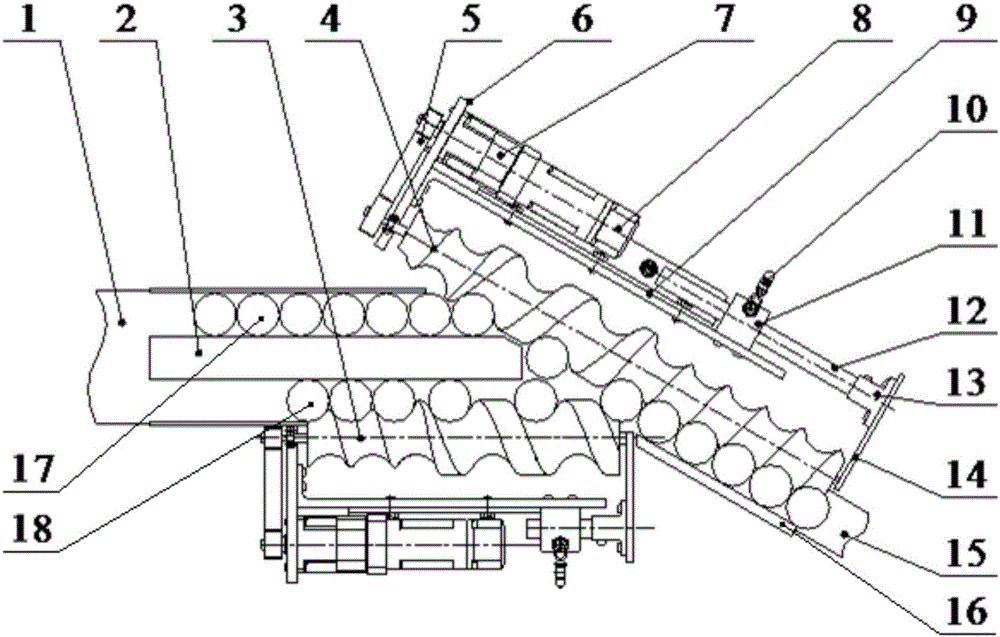
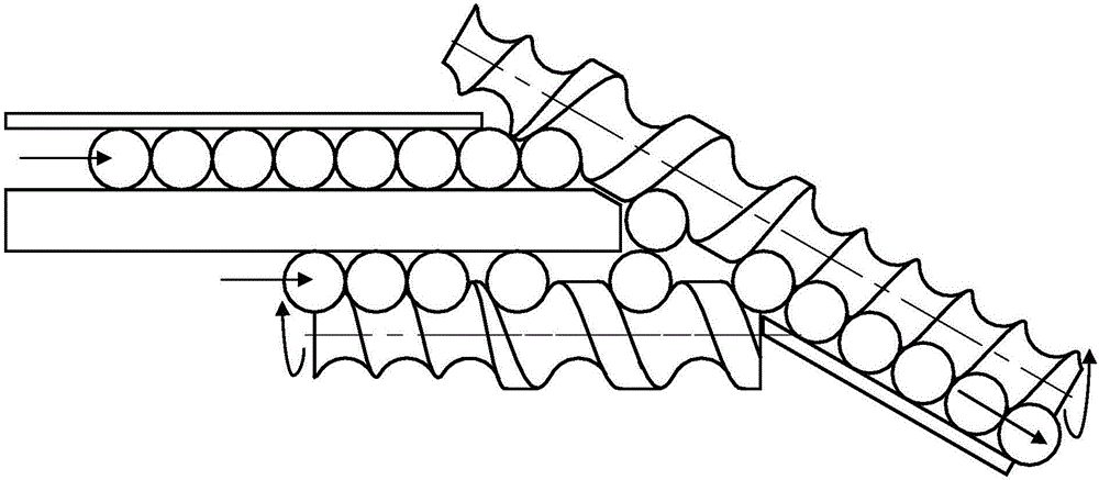
[0024] Such as Figure 1 to Figure 4 Shown is the structure of an embodiment of the present invention, a continuous material confluence conveying device based on a special-shaped screw, including a conveyor belt 1, a feeding screw, a driving device and a supporting device; the driving device is used to drive the feeding The screw, feed screw and drive unit are detachably mounted on the support unit. The conveyor belt includes a feed conveyor belt 1 and a discharge conveyor belt 15, and the feed screw includes an introduction screw 3 and a confluence screw 4; the feed conveyor belt 1 is used to continuously transport two columns of identical and parallel rigid / Semi-rigid...


PUM


Abstract

The invention belongs to the technical field of material packaging and conveying equipment, and provides a continuous material flow collecting and conveying device based on special-shaped screw rods. The device comprises a feeding conveying belt, a discharging conveying belt, an introduction screw rod and a flow collecting screw rod; the introduction screw rod is the special-shaped screw rod which is located on one side of the upper end of the feeding conveying belt and is parallel to the feeding conveying belt, the flow collecting screw rod is the special-shaped screw rod which is located on one side of the upper end of the discharging conveying belt and is parallel to the discharging conveying belt, two rows of same-shape parallel conveyed materials are input from one ends of the two special-shaped screw rods, along with changes of the screw pitches and the groove depths of the two special-shaped screw rods, the two rows of parallel materials are collected into one row alternatively, and the materials are output of the other end of the flow collecting screw rod; the screw rod rotating speed is adjusted according to the production requirement, the device is matched with a production line, and the whole process is high in speed and stable, and free of motion rigid impact; modular design is adopted in the device, and the beneficial effects of being low in cost, simple and compact in structure, convenient to mount and debug, efficient, stable in performance and the like are achieved.

Description

technical field [0001] The invention relates to the technical field of material packaging and conveying equipment, in particular to a continuous material confluence conveying device based on a special-shaped screw. Background technique [0002] Commodities in modern society are increasingly competitive in trade and circulation. Under the premise of ensuring product quality, the form of product packaging is also changing with each passing day. Consumers have higher and higher requirements for commodity packaging. The coordinated combination of product appearance and function meets consumers' requirements. Packaging machinery is a mechanical device with a high degree of automation. It can greatly increase production efficiency, improve the production environment, reduce production costs, improve commodity grades, and increase product added value, thereby enhancing the market competitiveness of commodities and bringing greater social benefits. benefits and economic benefits. ...

Claims


Application Information

Patent Timeline
Patent Type & Authority Applications(China)
IPC IPC(8): B65G47/68B65G33/02
CPCB65G33/02B65G47/681
Inventor 赵德颖张连东
Owner YANSHAN UNIV
Why Eureka
Try Eureka