Liquid supply apparatus, image forming apparatus and liquid supply method
a technology of liquid supply apparatus and liquid supply method, which is applied in the direction of printing, other printing apparatus, etc., can solve the problems of large pressure loss, increased ink consumption of recording head, and prone to increase, so as to prevent sudden pressure variations and stable ejection from recording head
- Summary
- Abstract
- Description
- Claims
- Application Information
AI Technical Summary
Benefits of technology
Problems solved by technology
Method used
Image
Examples
first embodiment
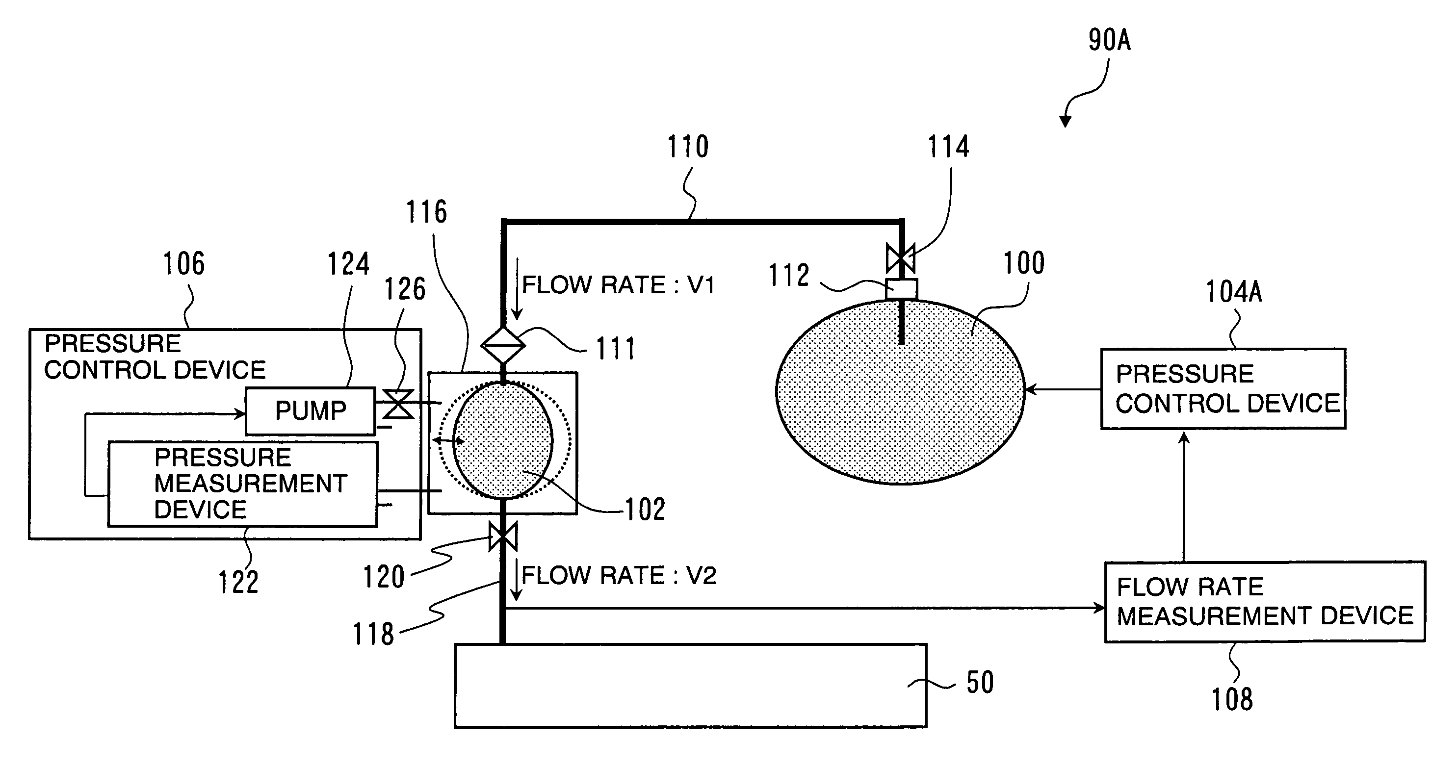
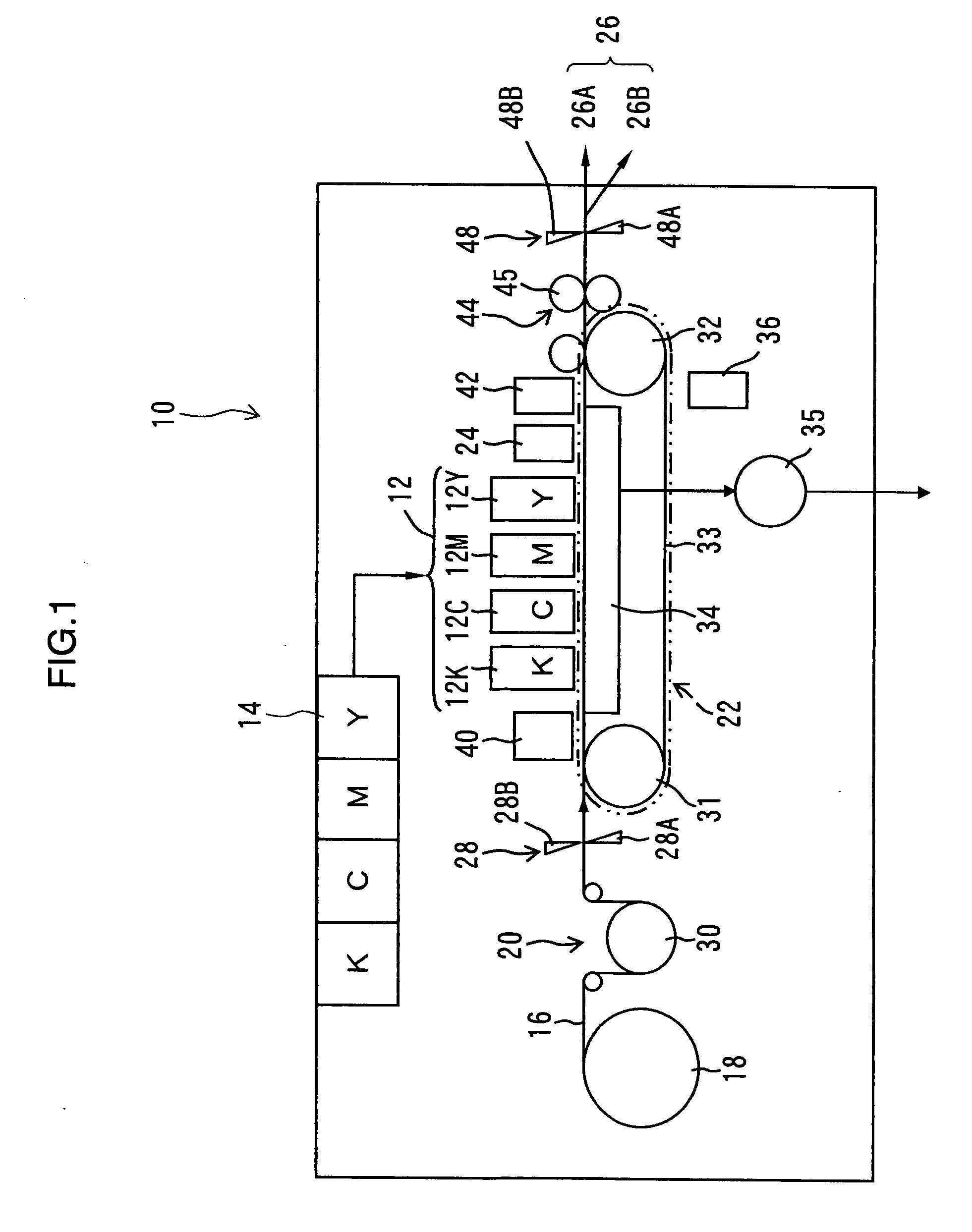
[0049]Firstly, an inkjet recording apparatus which forms the image forming apparatus according to an embodiment of the present invention is described below. FIG. 1 is a general schematic drawing showing an overall view of the inkjet recording apparatus. As shown in FIG. 1, the inkjet recording apparatus 10 includes: a print unit 12 having a plurality of recording heads 12K, 12C, 12M, and 12Y for ink colors of black (K), cyan (C), magenta (M), and yellow (Y), respectively; an ink storing and loading unit 14 for storing inks of K, C, M and Y to be supplied to the recording heads 12K, 12C, 12M, and 12Y; a paper supply unit 18 for supplying recording paper 16; a decurling unit 20 for removing curl in the recording paper 16; a suction belt conveyance unit 22 disposed facing the nozzle face (ink-droplet ejection face) of the print unit 12, for conveying the recording paper 16 while keeping the recording paper 16 flat; a print determination unit 24 for reading the printed result produced b...
second embodiment
[0119]Next, a second embodiment of the present invention is described. Below, the description of the parts of the second embodiment which are common to those of the first embodiment described above is omitted, and the explanation focuses on the characteristic features of the present embodiment.
[0120]FIG. 13 is a schematic drawing showing the composition of a liquid supply apparatus 90B according to the second embodiment of the present invention. The liquid supply apparatus 90B according to the second embodiment is different from the liquid supply apparatus 90A according to the first embodiment (shown in FIG. 6), in that the liquid supply apparatus 90B includes a liquid volume measurement device 132, as shown in FIG. 13.
[0121]The liquid volume measurement device 132 is a device which measures the amount of ink (liquid volume), S, in the sub tank 102. The measurement results (liquid volume S) obtained by the liquid volume measurement device 132 are reported to a first pressure control...
third embodiment
[0139]Next, a third embodiment of the present invention is described. Below, the description of the parts of this embodiment which are common to those of the above-described embodiments is omitted, and the explanation focuses on the characteristic features of the present embodiment.
[0140]FIG. 19 is a schematic drawing showing the composition of a liquid supply apparatus 90C according to the third embodiment of the present invention. The liquid supply apparatus 90C according to the third embodiment is different from the liquid supply apparatus 90A according to the first embodiment (see FIG. 6), in that the liquid supply apparatus 90C includes an operational history storage device 134, as shown in FIG. 19.
[0141]The operational history storage device 134 is a device which stores the operational history of the pump 124. In the present embodiment, a rotary pump is used as the pump 124. The operational history of the pump 124 includes an operating time of the pump 124. The operating time ...
PUM
 Abstract
Description
Claims
Application Information
 - R&D
- Intellectual Property
- Life Sciences
- Materials
- Tech Scout
- Unparalleled Data Quality
- Higher Quality Content
- 60% Fewer Hallucinations
Browse by: Latest US Patents, China's latest patents, Technical Efficacy Thesaurus, Application Domain, Technology Topic, Popular Technical Reports.
© 2025 PatSnap. All rights reserved.Legal|Privacy policy|Modern Slavery Act Transparency Statement|Sitemap|About US| Contact US: help@patsnap.com


