Method for detecting printing material amounts in printing material container attached to printer

Inactive Publication Date: 2008-01-10
SEIKO EPSON CORP
View PDF0 Cites 5 Cited by
  • Summary
  • Abstract
  • Description
  • Claims
  • Application Information

AI Technical Summary

Benefits of technology

[0008]The present invention is implemented in view of the above problems, and the purpose thereof is to improve the accuracy of the determination of the amount of ink stored in the ink container.
[0017]According to the printer of the first aspect of the present invention, it is able to determine the amount of the printing material stored in the printing material container by referencing a first vibration frequency that is measured using a driving signal having a first frequency, and referencing a second vibration frequency that is measured using a driving signal that has a second frequency that is lower than the first frequency. The printer in accordance with the present invention is able to improve the accuracy of the determination of the amount of printing material, even when the natural frequency of the printing material container has changed.
[0025]The printer in accordance with the second aspect of the present invention is able to acquire the first frequency and the second frequency using a simple structure because the first frequency and the second frequency themselves are stored in the memory. Consequently, the use of the printer in accordance with the second aspect of the present invention is both able to reduce the time required for the process of determining the amount of ink, and able to increase the accuracy of the determination.
[0033]The printer in accordance with the third aspect of the present invention is able to acquire the first frequency and the second frequency with ease based on a reference natural frequency, making it possible to determine the amount of printing material that is stored in the printing material container by referencing the first vibration frequency and the second vibration frequency using the first frequency and the second frequency. Thus the printer is able to improve the accuracy of the determination of the amount of printing material even when there is a change in the value of the natural frequency of the printing material container.
[0045]The system of the forth aspect of the present invention is able to determine the amount of printing material stored in the printing material container based on the first vibration frequency and the second vibration frequency measured using a driving signal having two different frequencies. Thus the system is able to improve the accuracy of the determination of the amount of printing material even when the natural frequency of the printing material container has changed.

Problems solved by technology

For example, there are changes caused by the ink that is adhered to the sensor when the ink stored in the ink container remains in the ink container at less than a specific amount, and changes caused by damage to the sensor part in the ink container.
When the natural frequency changes, the accuracy of the measured vibration frequency drops because it is not possible to obtain an adequate amplitude in the vibration of the sensor.
As a result, the accuracy of the measurement of the ink volume reduces.

Method used


Image

  • Method for detecting printing material amounts in printing material container attached to printer
  • Method for detecting printing material amounts in printing material container attached to printer
  • Method for detecting printing material amounts in printing material container attached to printer

Examples


first embodiment

A. First Embodiment

A1. System Structure:

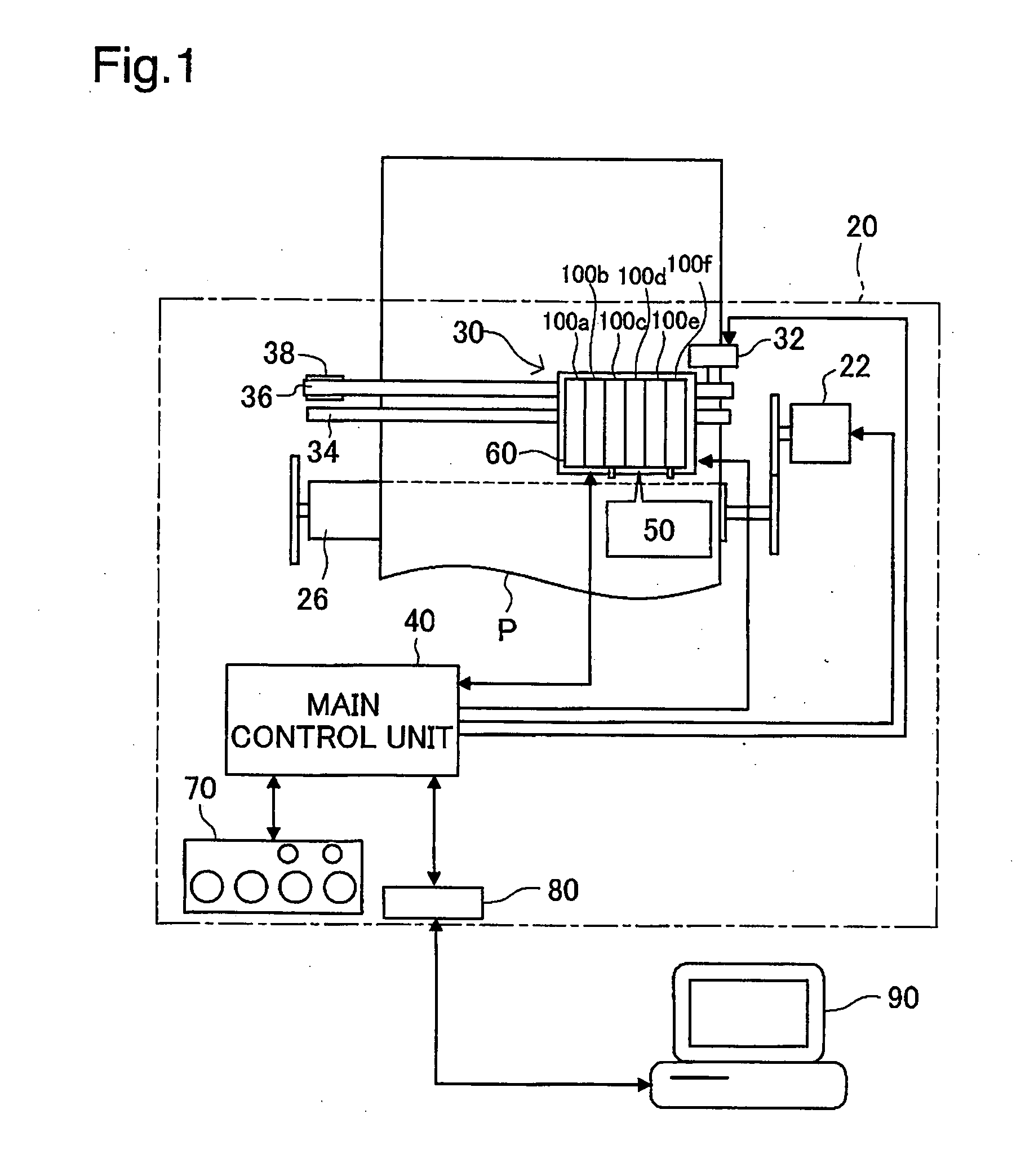
[0060]FIG. 1 is used to explain the basic structure of a printing system in an embodiment. FIG. 1 illustrates an explanatory diagram of the basic structure of the printing system. The printing system comprises a printer 20 and a computer 90. The printer 20 is connected to the computer 90 through a connector 80.

[0061]The printer 20 comprises a secondary scanning mechanism, a primary scanning mechanism, a head controlling mechanism, and a main controller 40 for controlling the various mechanisms. The secondary scanning mechanism comprises a paper feeding motor 22 and a platen 26. The secondary scanning mechanism feeds the paper P in the secondary scanning direction by transmitting, to the platen, the rotation of the paper feeding motor. The primary scanning mechanism comprises a carriage motor 32, a pulley 38, a driving belt 36 that stretches between the carriage motor 32 and the pulley 38, and a slide rod 34 that is disposed in parallel with th...

second embodiment

B. Second Embodiment

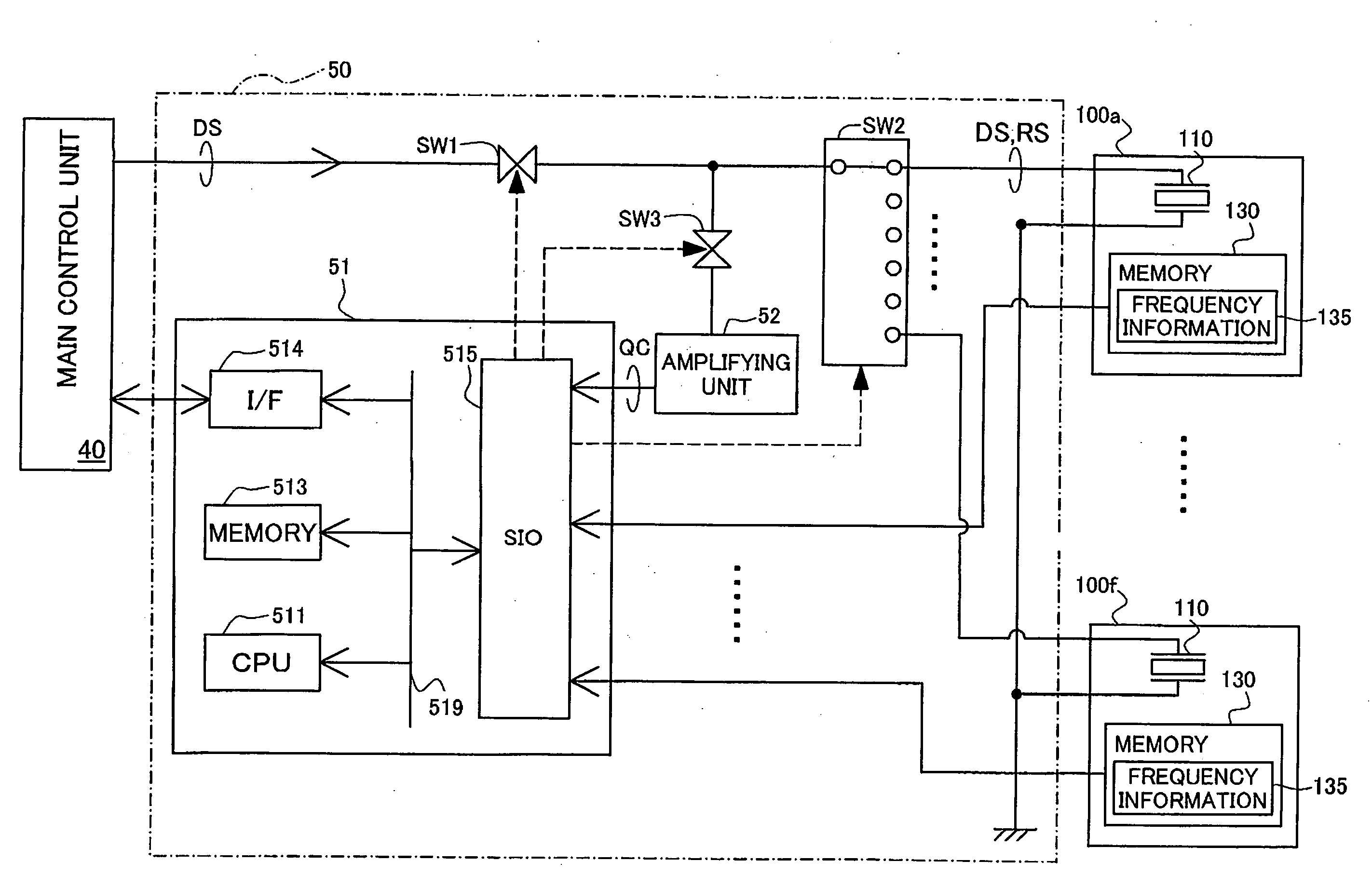
[0132]The first embodiment, described above, included the natural frequency for when there is no ink from the time that the ink cartridge was manufactured. In the second embodiment, the following form is presented. A printer 20 of the second embodiment is provided in advance with a frequency table that associates a plurality of vibration frequency ranges wherein the tolerance range ER2 is divided into a plurality of ranges, with the first frequency F1 and the second frequency F2 for each vibration frequency range. The memories in each of the ink cartridges in the second embodiment contain rank information indicating the vibration frequency range wherein the natural frequency HE is included in the ink end state in the individual ink cartridge. The printer 20 determines the frequency of the driving signal based on the rank information that is stored in the memory for the cartridge to be processed, and based on the rank table. Note that the system structure in the s...


PUM


Abstract

The amount of ink is determined using both a first vibration frequency VF1 that is measured when a driving signal DS1 of a first frequency is provided to a sensor, and a second vibration frequency VF2 that is measured when a driving signal DS2 of a second frequency F2, which is less than the first vibration frequency by a specific ratio, is provided to the sensor. When there is an incorrect measurement of either the first vibration frequency VF1 or the second vibration frequency VF2, the natural frequencies to which the vibration frequencies are near will be different, as shown in the combination numbers “2” and “3” in the Ink Amount of Determining Table 600. Because the cases wherein the vibration frequency is measured incorrectly are the cases wherein there is no ink, when the first vibration frequency VF1 and / or the second vibration frequency VF2 is near to the target natural frequency H2 (combination numbers “2” through “4”), it is determined that the amount of ink is stored in the cartridge being processed is less than a specific amount.

Description

CROSS-REFERENCE TO RELATED APPLICATIONS[0001]The present application claims the priority based on Japanese Patent Application No. 2006-158423 filed on Jun. 7, 2006, the disclosure of which is hereby incorporated by reference in its entirety.BACKGROUND[0002]1. Technical Field[0003]The present invention relates to printers, and, in particular, relates to methods for detecting printing material amounts in printing material containers attached to printers.[0004]2. Related Art[0005]Ink containers attached to ink-spray printers are provided with sensors for detecting the amount of remaining ink, such as piezoelectric elements having the characteristics of expanding and contracting when a voltage is applied. Because piezoelectric elements generate a residual vibration after a voltage has been applied and then output an output signal by this residual vibration, when the amount of ink is detected using a sensor provided with a piezoelectric element, the printer is able to determine whether t...

Claims


Application Information

Patent Timeline
IPC IPC(8): B41J29/38
CPCB41J2/17566
Inventor JUNHUA, ZHANG
Owner SEIKO EPSON CORP
Why Eureka
Try Eureka