
Photochromic compound and optical functional material

a technology of optical functional materials and compound compounds, applied in the field of photochromic compound and optical functional materials, can solve the problems of low colorability of substances, weak durability, and the inability to use silver salts for glass, and achieve the effect of improving colorability and lowering the quantum yield of fading reactions

Inactive Publication Date: 2008-01-10
NARA INSTITUTE OF SCIENCE AND TECHNOLOGY
View PDF0 Cites 6 Cited by
  • Summary
  • Abstract
  • Description
  • Claims
  • Application Information

AI Technical Summary

Benefits of technology

[0013]An objective of the present invention is to provide a photochromic compound having an improved thermo-fading speed while maintaining the advantageous photochromic properties due to the diarylethene skeleton.
[0021]The photochromic compound according to the present invention described thus far has a high quantum yield and is quick to be thermally faded. It can be faded with visible light and is highly dispersible into plastic macromolecular materials. Therefore, the present photochromic compound is suitable as optical functional materials for high-response dimming devices, such as sunglasses or visors for car drivers.BEST MODES FOR CARRYING OUT THE INVENTION
[0027]In the general formula (I), B1 and B2 are functional groups identical to or different from each other, each group having an atomic number of five or larger, including a ring compound, and bonded to the 2-carbon of each of A2 and A3, respectively. For the reason explained previously, B1 and B2 should be preferably π-conjugated substituents. Furthermore, B1 and B2 should preferably have a rigid molecular frame including, for example, a triple bond. This condition improves the frequency factor and thereby enhances the thermo-fading speed.
[0031]In the photochromic compound according to the present invention, the color of the compound in the colored state, i.e. the light absorption characteristics of the compound expressed by the general formula (II), can be regulated by the choice of R1 in the general formula (I) (or (II)). Accordingly, in the photochromic compound according to the present invention, the structure of R1 should not be limited; it is preferable to choose the structure according to the intended use of the compound. However, it should be noted that use of a substituent having many π-conjugate electrons will make the compound highly colorable. Examples of R1 include phenyl, thiophene, naphthyl and other aryl groups, and alkyl groups. Oligothiophene and phenylenevinylene are also available.
[0032]R2 and R3 may be identical to or different from each other. They are bonded to the carbon atom at the α-position of A2 and A3, except the carbon at the reaction site. The photochromic compound according to the present invention changes its color in the colored state when R2 or R3 is replaced with a different functional group. Accordingly, none of R2 and R3 should be limited to specific functional groups. However, it should be noted that using a group having many π-conjugated electrons as R2 or R3 will lower the quantum yield of the fading reaction caused by visible light and thereby improve the colorability. Examples of the functional groups available as R1 or R2 in the present invention include phenylethynyl, thiophene, phenylenevinylene and thienylenevinylene.

Problems solved by technology

However, silver salt can be used only for glass.
However, this substance is low in colorability and weak on durability.
From practical viewpoints, however, the period of 20 seconds is still too long as the thermo-fading time.
For example, this photochromic compound is unsuitable for sunglasses because wearing such sunglasses will be dangerous for car drivers, especially when the car is on a road with many tunnels.
Moreover, fading this compound requires a temperature of 100 degrees Celsius or even higher, which is impractical.

Method used


Image

  • Photochromic compound and optical functional material
  • Photochromic compound and optical functional material
  • Photochromic compound and optical functional material

Examples


examples

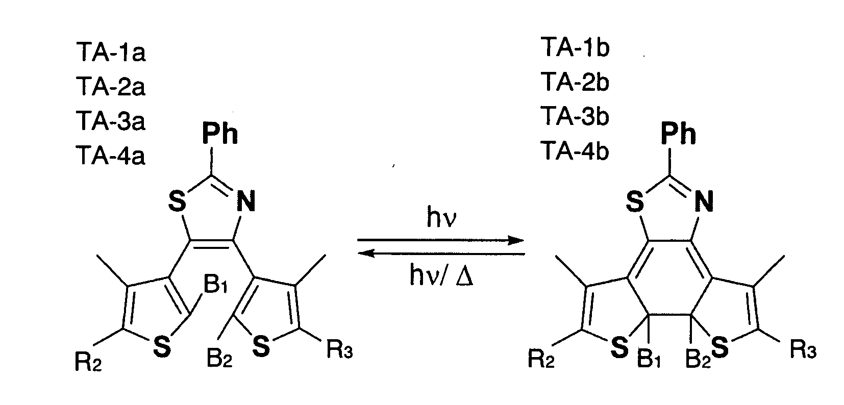
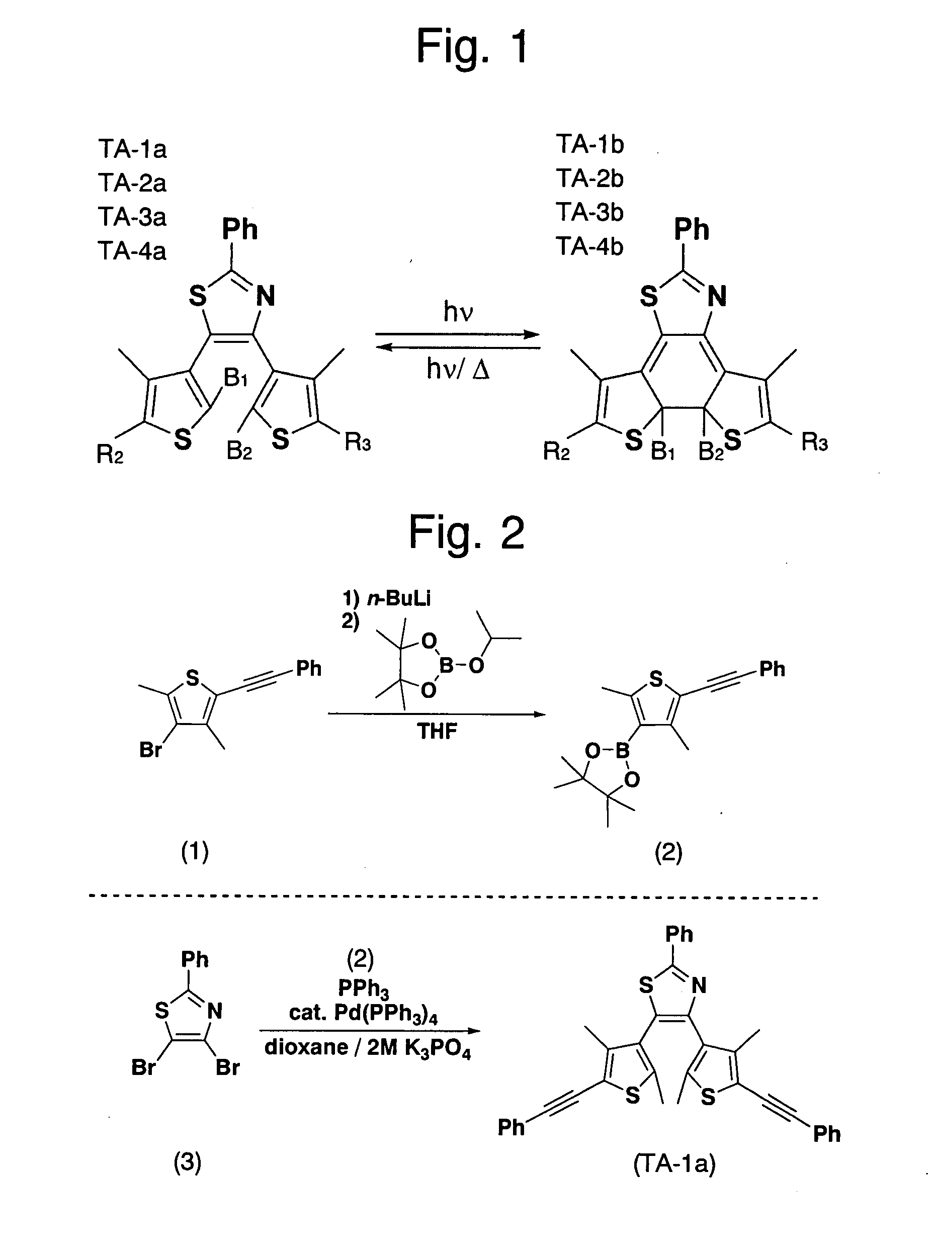
[0048]Four compounds (TA-1a, TA-2a, TA-3a and TA-4a) as shown in FIG. 1, all expressed by the general formulas (I) and (II) have been prepared, including phenyl as R1, thiazole as A1 and thiophene as A2 and A3, to examine and compare their characteristics. Each compounds contained the substituents B1, B2, R2, and R3 as follows:

TA-1a . . . B1 and B2: methyl, B1 and B2: phenyl.

TA-2a . . . B1: methyl, B2: phenylethynyl, R2: phenyl, R3: phenylethynyl

TA-3a . . . B1: phenylethynyl, B2: methyl, R2: phenylethynyl, R3: phenyl

TA-4a . . . B1, B2, R2 and R3: phenylethynyl

[0049]The compounds TA-1a through TA-4a were synthesized by Suzuki-Miyaura coupling reactions of a dibromo-form of A1 and boron derivatives of A2 and A3 under the catalytic influence of palladium. The reaction of producing TA-3 and TA-2, which were bilaterally asymmetrical, was conducted in steps taking into account the fact that thiazole is more reactive at the 5-carbon than at the 4-carbon.

[0050]Referring to FIG. 2, the metho...


PUM

PropertyMeasurementUnit
Nanoscale particle sizeaaaaaaaaaa

Abstract

The present invention provides a photochromic compound that is colored when irradiated with visible light and quickly faded when set in a dark place. The photochromic compound according to the present invention is expressed by the following general formula (I):where each of A1, A2 and A3 is a five-member rings forming a 6π-electron system, the three rings being identical, partially identical or totally different from each other, and each ring may have a substituent; B1 and B2 are functional groups, each having an atomic number of five or larger, including a ring compound, and bonded to the 2-carbon of each of A2 and A3, respectively; and R1, R2 and R3 are substituents identical to or different from each other. This compound is highly colorable and durable even when it is dispersed into plastic macromolecular materials. Therefore, it is suitable as a dye material for sunglasses or similar products.

Description

[0001]The present invention relates to a photochromic compound. Particularly, it relates to a photochromic compound that allows fast thermal fading rate.BACKGROUND OF THE INVENTION[0002]Photochromic substances are such materials whose molecules reversibly isomerized when they are irradiated with light.[0003]One of the photochromic substances conventionally studied by many people is diarylethene. FIG. 15 shows the structural formula of a diarylethene molecule. Diarylethene turns to a colored state when it is irradiated with ultraviolet light and to a faded state (i.e. the original state) when it is irradiated with visible light. In addition to this photochromic property, diarylethene has the following characteristics:[0004]It has a high quantum yield. That is, it is quick to change its color and highly colorable.[0005]It is very reactive when it is in a polymer. Therefore, it can be easily fused with various materials.[0006]It is durable. The coloring and fading properties scarcely d...

Claims


Application Information

Patent Timeline
IPC IPC(8): G02B5/23C07D207/00C07D209/04C07D233/54C07D263/00C07D275/00C07D333/00
CPCG02B5/23C07D417/14
Inventor KAWAI, TSUYOSHINAKAJIMA, TAKUYAKAWAI, SHIGEKAZU
Owner NARA INSTITUTE OF SCIENCE AND TECHNOLOGY
Learn More