Vehicle

Inactive Publication Date: 2008-01-03
MALLAGHAN RONAN
View PDF13 Cites 2 Cited by
  • Summary
  • Abstract
  • Description
  • Claims
  • Application Information

AI Technical Summary

Benefits of technology

[0004]While these methods are effective to achieve the desired result, they involve either the use of two operators resulting in increased costs for the airline operators or considerable manual labour for a single luggage handler who must both carry the luggage and load / unload the luggage. It is an object of the present invention to provide an apparatus to overcome the requirement for two operators to load and unload passenger luggage from a baggage cart to and from an aeroplane and to reduce the workload for the remaining single operator.
[0064]Advantageously, when the tow bar is in its first substantially horizontal position, the vehicle is towable and the towing turntable and towing axis provide steering assistance to the operator of the towing vehicle. When the towing vehicle has delivered the vehicle to the site for loading and unloading, an operator can raise the tow bar into its second substantially vertical position which fixes the towing turntable and towing axle relative to the chassis so that the longitudinal axis of the towing axle is perpendicular to the longitudinal axis of the chassis. At this point, the operator can operate the combined steering control means and wheel drive means to accurately locate the vehicle adjacent the loading / unloading area without the need of a towing vehicle.

Problems solved by technology

While these methods are effective to achieve the desired result, they involve either the use of two operators resulting in increased costs for the airline operators or considerable manual labour for a single luggage handler who must both carry the luggage and load / unload the luggage.

Method used


Image

  • Vehicle
  • Vehicle
  • Vehicle

Examples


first embodiment

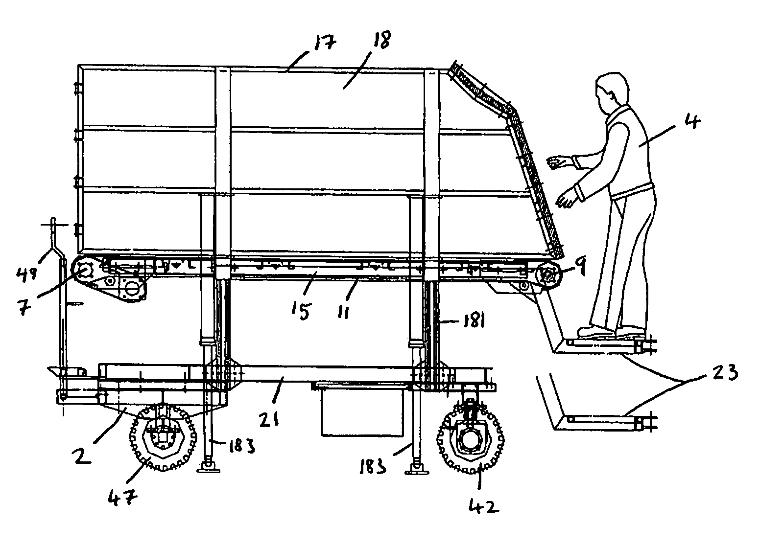
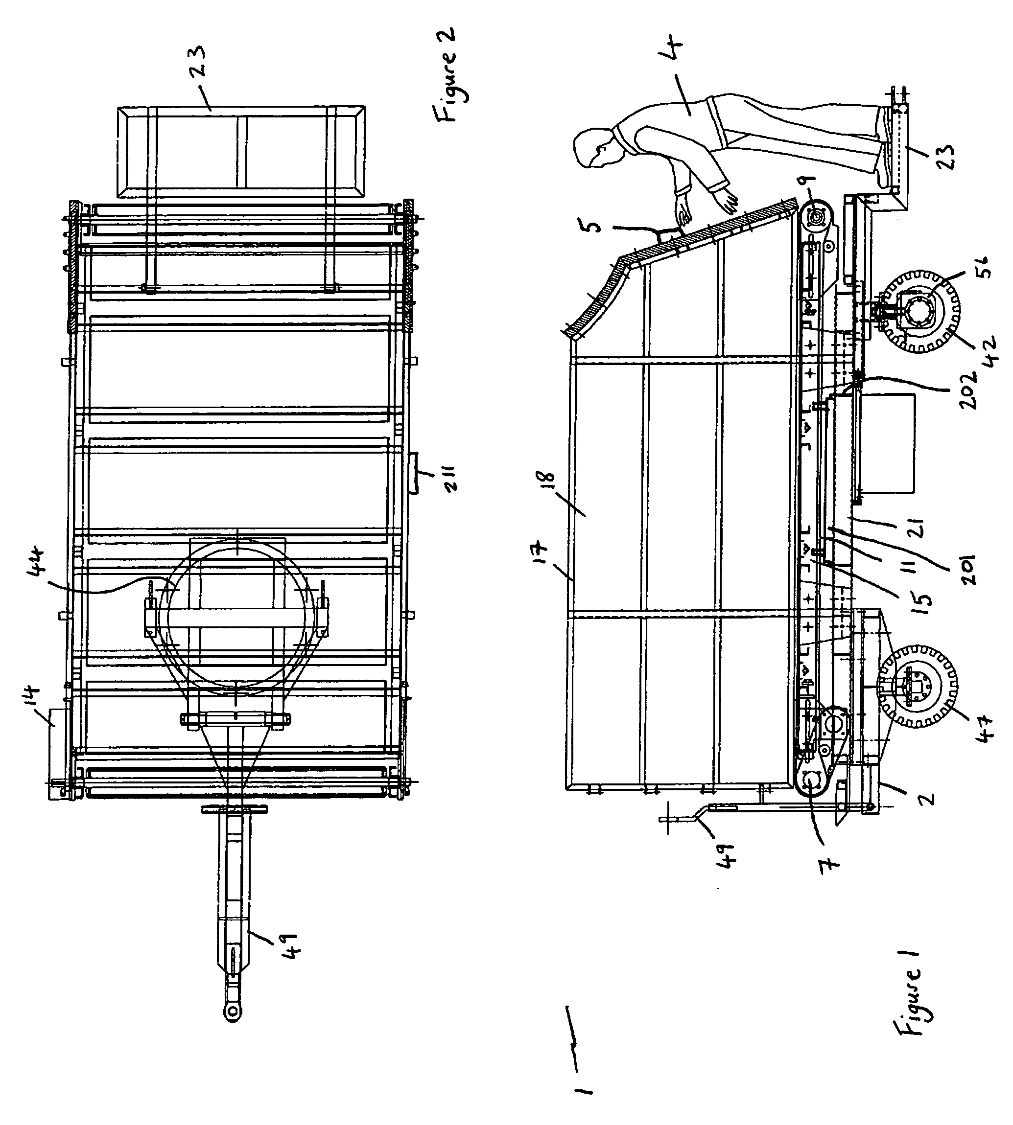
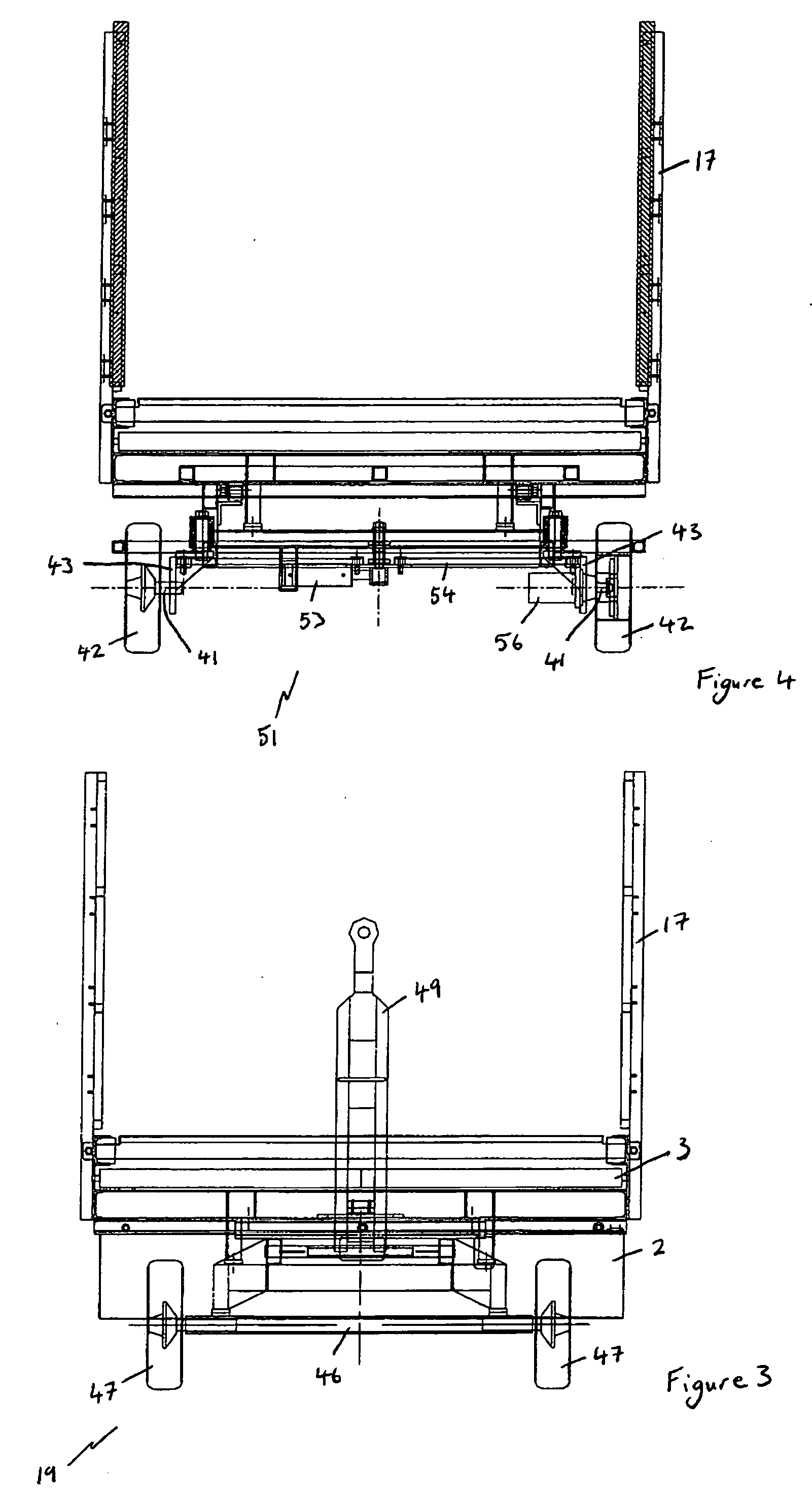
[0079]Referring to FIGS. 1 to 4 of the drawings, there is shown a vehicle indicated generally by the reference numeral 1 having a carriage 2 for transporting the vehicle 1 along the ground and a conveyor arrangement 3 mounted on the carriage 2 for conveying articles (not shown) away from or towards an operator 4 who is loading or unloading the articles to or from the vehicle 1. The vehicle 1 is a baggage handling apparatus and the baggage handling apparatus is towable. The articles are generally items of luggage.

[0080]Advantageously, the conveyor arrangement 3 of the towable baggage handling apparatus allows a single operator 4 to unload and stack a row of luggage on the conveyor arrangement 3 adjacent the point where the operator 4 is standing. When the space on the conveyor arrangement 3 adjacent the operator 4 is packed with bags the operator 4 can manually operate the conveyor arrangement 3 to move the stacked luggage away from themselves providing new space for further luggage ...

second embodiment

[0096]In vehicle 101 shown in FIGS. 5 to 7 of the drawings, the same reference numerals have been used to reference features similar to those of FIGS. 1 to 4 and the conveyor arrangement 3 is vertically movable relative to the carriage 2. Hydraulic rams 181 are mounted intermediate the conveyor arrangement 3 and the carriage 2. Two pairs of hydraulic rams 181 are mounted on longitudinally spaced apart and mutually opposing locations along opposite lateral edges of the conveyor arrangement 3 and the carriage 2. Stabilising members are mounted on the vehicle 101 and the stabilising members are provided by hydraulically actuated stabilising jacks 183 mounted between the conveyor arrangement 3 and the ground in use. Two pairs of stabilising jacks 183 are mounted on longitudinally spaced apart and mutually opposing locations along opposite lateral edges of the conveyor arrangement 3 and the carriage 2. A separate hydraulic control unit is provided for the stabilising members.

[0097]In a t...


PUM


Abstract

A vehicle comprising carriage means for transporting the vehicle along the ground and conveyor means mounted on the carriage means for conveying at least one article along the conveyor means.

Description

FIELD OF THE INVENTION [0001]The present invention relates to a vehicle and in particular to a towable baggage handling apparatus for assisting an operator during loading and unloading of baggage to and from an aeroplane.SUMMARY OF THE INVENTION [0002]The present method of loading and unloading passenger baggage to and from aeroplanes involves the delivery of a towable baggage cart to a location adjacent the cargo storage area of an aeroplane by a powered vehicle. During unloading, a first operator stands at a first end of the baggage cart beside the open door of the cargo storage area of the aeroplane and lifts the luggage from the baggage storage area of the aeroplane onto the first end of the baggage cart. A second operator then lifts the luggage from the first end of the baggage cart and carries it to the second end of the baggage cart and begins to stack the luggage at the second end. This procedure continues until either all of the luggage has been removed from the storage are...

Claims


Application Information

Patent Timeline
IPC IPC(8): B60P1/00
CPCB64F1/32B64F1/324
Inventor MALLAGHAN, RONAN
Owner MALLAGHAN RONAN
Why Eureka
Try Eureka