Droplet discharging device and ink jet printer

a technology of ink jet printer and discharging device, which is applied in printing and other directions, can solve the problems of clogging of discharging openings with small opening areas more readily than clogging, and achieve the effect of suppressing the clogging of the second discharging opening and preventing the liquid from drying ou

Inactive Publication Date: 2008-01-03
BROTHER KOGYO KK
View PDF9 Cites 1 Cited by
  • Summary
  • Abstract
  • Description
  • Claims
  • Application Information

AI Technical Summary

Benefits of technology

[0011]With this droplet discharging device, the barometric pressure within the cap covering the second discharging opening can be set to be a value within a range in which the breakdown stress of the meniscus formed in the second discharging opening is not exceeded. The barometric pressure within the cap covering the first discharging opening can be set to be a value within a range in which the breakdown stress of the meniscus formed in the first discharging opening is not exceeded. In this droplet discharging device, the meniscus formed in the first discharging opening is not damaged, and it is possible to suppress the drying out of the liquid near the second discharging opening having a small opening area. As a result, it is possible to suppress the blockage of the second discharging opening having a small opening area.

Problems solved by technology

And now, discharging openings that have small opening areas become blocked more readily than discharging openings that have large opening areas because the liquid near the discharging opening dries out.

Method used


Image

  • Droplet discharging device and ink jet printer
  • Droplet discharging device and ink jet printer
  • Droplet discharging device and ink jet printer

Examples


first embodiment

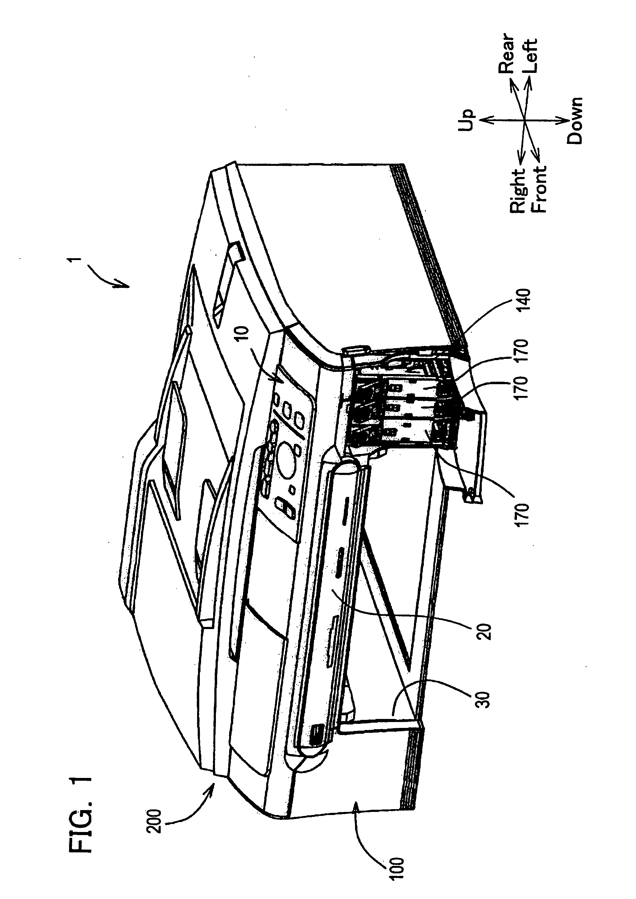
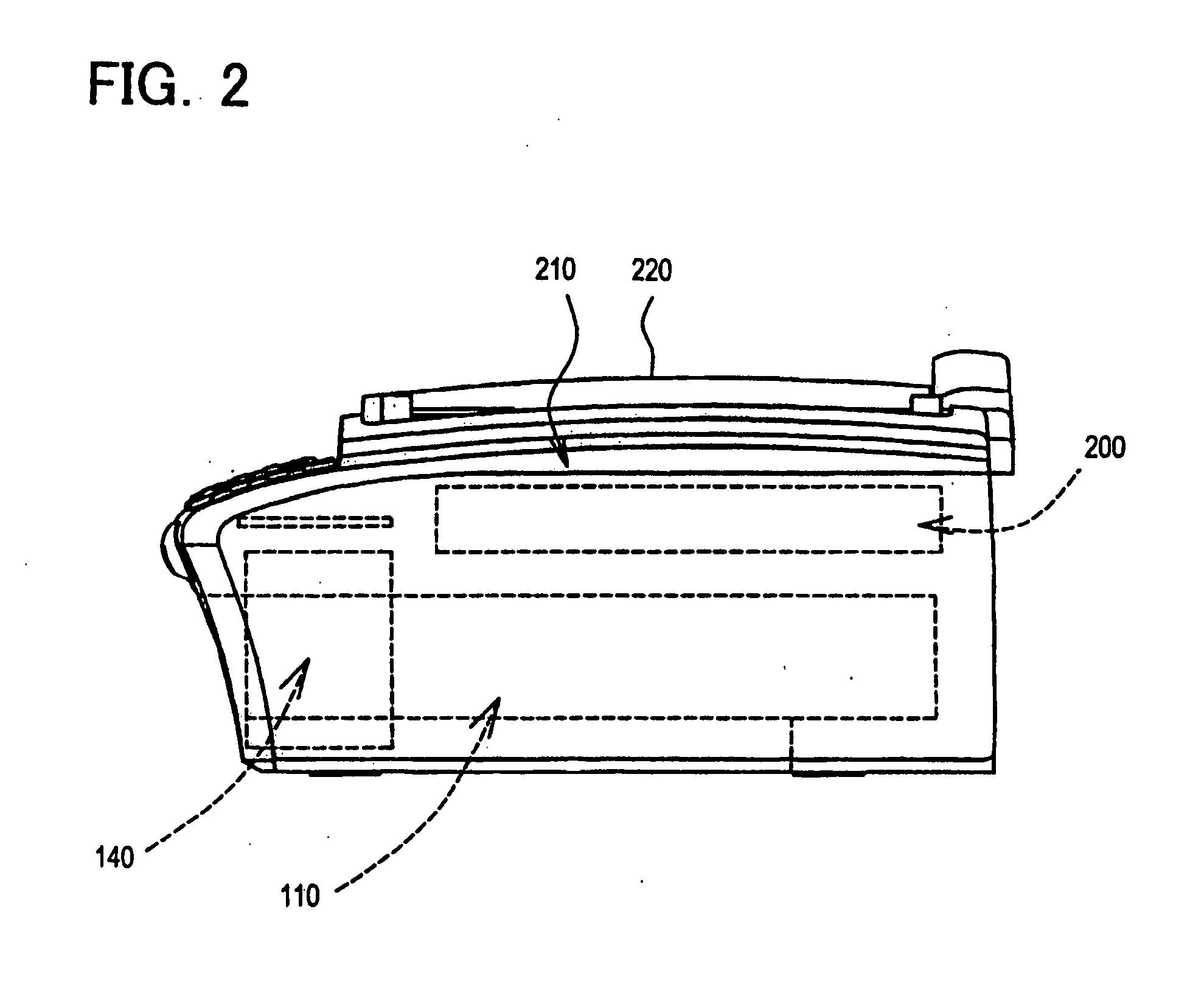
[0019]A multi function device including a droplet discharging device of a first embodiment will be described below with reference to the figures. FIG. 1 shows an external perspective view of the multi function device of the first embodiment. FIG. 2 shows a side surface view of the multi function device 1. The portion surrounded by the broken line in FIG. 2 shows devices and equipment housed within the multi function device 1. In the present embodiment, the droplet discharging device and an ink jet recording device are suitable for a multi function device provided with a scanner function, a copy function, a facsimile function, etc.

[0020]Furthermore, the multi function device 1 of the present embodiment is capable of being connected to a computer. The multi function device 1 is capable, on the basis of image data or document data transmitted from the computer, of recording image data that includes letters on a recording medium (hereafter termed recording paper) consisting of recording...

second embodiment

[0047]In the first embodiment, the first cap 151 and the second cap 152 are moved by the single actuator 160. However, an actuator may be provided for each cap.

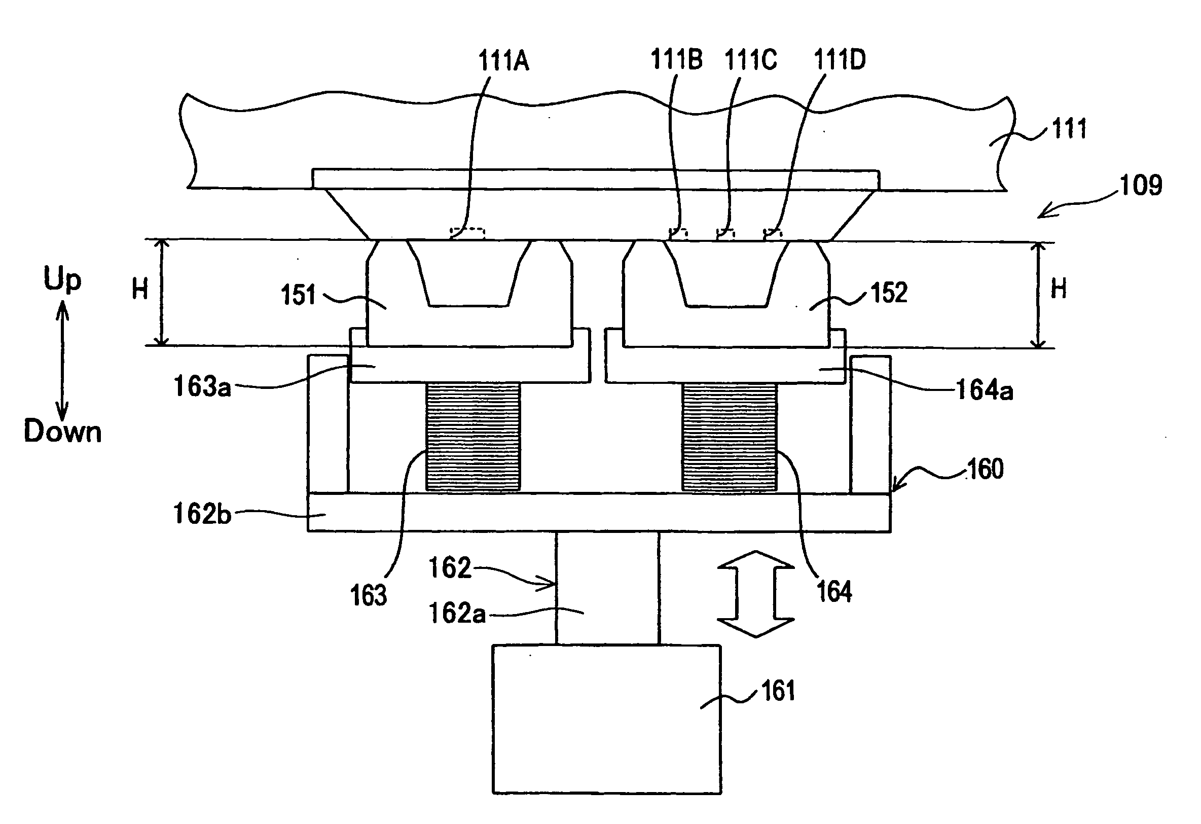
[0048]The configuration of an actuator of the second embodiment will be described with reference to FIG. 7. With the exception of the actuator, the multi function device of the second embodiment is the same as the multi function device of the first embodiment. Hereinafter, only the actuator will be described. FIG. 7 shows a front view of an ink discharging device 109 of the multi function device 1 of the present embodiment. FIG. 7 shows a state where the first cap 151 and the second cap 152 are in the first position. As shown in FIG. 7, a first actuator 160A for the first cap 151, and a second actuator 160B for the second cap 152 are provided. The spring part 163 is disposed between the first cap 151 and the first actuator 160A. The spring part 163 is supported by a first spring supporting part 162A. The spring part 164 is di...


PUM


Abstract

A droplet discharging device is provided with a discharging head, a first cap, a second cap and a barometric pressure controlling device. The discharging head has a first discharging opening and a second discharging opening. The second discharging opening is smaller than the first discharging opening. The first cap is capable of making contact with the discharging head and covering the first discharging opening. The second cap is capable of making contact with the discharging head and covering the second discharging opening. The barometric pressure controlling device controls a first barometric pressure within the first cap making contact with the discharging head and a second barometric pressure within the second cap making contact with the discharging head such that the second barometric pressure is greater than the first barometric pressure.

Description

CROSS-REFERENCE TO RELATED APPLICATION[0001]This application claims priority to Japanese Patent Application No. 2006-181775, filed on Jun. 30, 2006, the contents of which are hereby incorporated by reference into the present application.BACKGROUND OF THE INVENTION[0002]1. Field of the Invention[0003]The present invention relates to a droplet discharging device that discharges liquid in the form of droplets. Furthermore, the present invention relates to an ink jet printer utilizing this droplet discharging device.[0004]2. Description of the Related Art[0005]A droplet discharging device utilized in an ink jet printer or the like comprises a discharging head. The discharging head comprises a pressing device and a discharging opening. The pressing device applies pressure to a liquid such as ink or the like within the discharging head by means of, for example, deforming a piezoelectric element, changing the volume of a bubble by means of a thermal resistor, etc. The liquid to which press...

Claims


Application Information

Patent Timeline
Patent Type & Authority Applications(United States)
IPC IPC(8): B41J2/165
CPCB41J2/16508B41J2/2125
Inventor UMEDA, TAKAICHIRO
Owner BROTHER KOGYO KK
Why Eureka
Try Eureka