
Method and apparatus for preventing overinsertion in plastic pipe systems

a technology of plastic pipe and over-insertion, applied in the direction of hose connection, sleeve/socket joint, pipe-joint, etc., to achieve the effect of reducing the cost of sealing, ensuring the integrity of the pipe, and being reliable in operation

Inactive Publication Date: 2008-01-03
S & B TECHN PRODS
View PDF22 Cites 25 Cited by
  • Summary
  • Abstract
  • Description
  • Claims
  • Application Information

AI Technical Summary

Benefits of technology

[0013] It is therefore an object of the present invention to provide a method and apparatus for preventing overinserton of plastic pipe in forming sealed connections in pipeline installations which is simple in design and dependable in operation and which does not add greatly to the cost of the sealing and restraining systems presently employed in the relevant industries.
[0014] In the method and apparatus of the invention, a female plastic pipe end having a belled end is both joined and sealed with a mating male plastic pipe end having an interior surface and an exterior surface. A sealing element is provided in the form of an elastomeric sealing gasket, the gasket being installed within an internal groove formed in the belled end of the female pipe section. Next, the male pipe end is inserted into the belled end of the female pipe end so that the elastomeric sealing gasket makes sealing contact with the exterior surface of the male pipe. A special control mechanism is provided for controlling the distance the male pipe travels longitudinally within the belled end of the female plastic pipe to thereby prevent overinsertion of the male pipe within the female pipe opening.
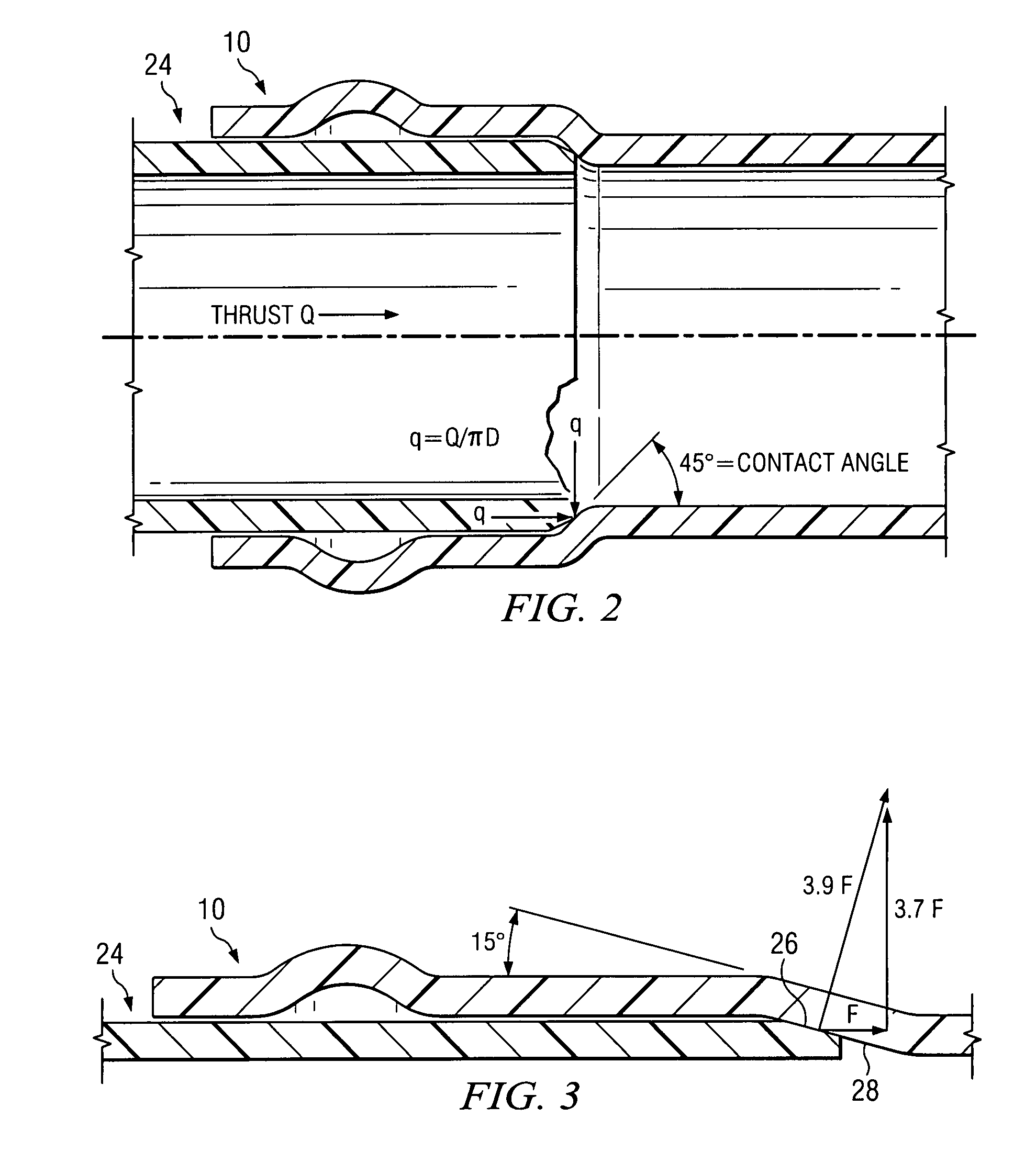
[0016] In another version of the invention, the female pipe bell end forms an internal socket with a socket bottom wall. An interface angle exists between the male pipe end exterior surface and the socket bottom wall. The interface angle is increased by a predetermined amount in order to provide the control mechanism for preventing overinsertion of the male pipe within the female pipe opening.
[0017] A companion restraint mechanism can also be provided for the elastomeric sealing ring which allows movement of the mating male pipe relative to the belled end of the female pipe in a first longitudinal direction but which restrains movement in a second, opposite relative direction. The restraint mechanism may also be provided with an internal shoulder which serves as an internal stop for preventing overinsertion of the male pipe within the female pipe opening. In one form of the invention, the restraint mechanism is located in the groove formed in the belled end of the female pipe section and the sealing gasket is joined to the restraint mechanism and trails outwardly from the internal groove formed in the belled pipe end along a longitudinal axis of the female pipe.
[0018] In yet another version of the invention, a special coupling is provided for joining a first and second male pipe ends. The coupling has opposing end openings each provided with a sealing groove and an installed sealing gasket. The coupling also has a centrally located stop for controlling the distance each of the male pipes travels longitudinally within the respective end openings of the coupling to thereby prevent overinsertion of the male pipe within the female pipe opening.

Problems solved by technology

In addition to the problem of restraining plastic pipe joints to prevent separation of the joints in use or failure of the seal systems thereof, a separate problem is that of possible overinsertion of the male, spigot pipe end into the mating female, belled pipe end during assembly of the pipe sections into a pipeline installation.
Various pipeline failure analyses have been traced back to excessive stresses on the bell pipe end as a result of overinsertion of the male pipe end.
In spite of the fact that possible overinsertion of PVC pipe is understood to be the cause of failure in some pipeline installations, to Applicant's knowledge, no current technology exists to address this problem in the same way that various technologies exist to address the problem of restrained joints.

Method used


Image

  • Method and apparatus for preventing overinsertion in plastic pipe systems
  • Method and apparatus for preventing overinsertion in plastic pipe systems
  • Method and apparatus for preventing overinsertion in plastic pipe systems

Examples


Embodiment Construction

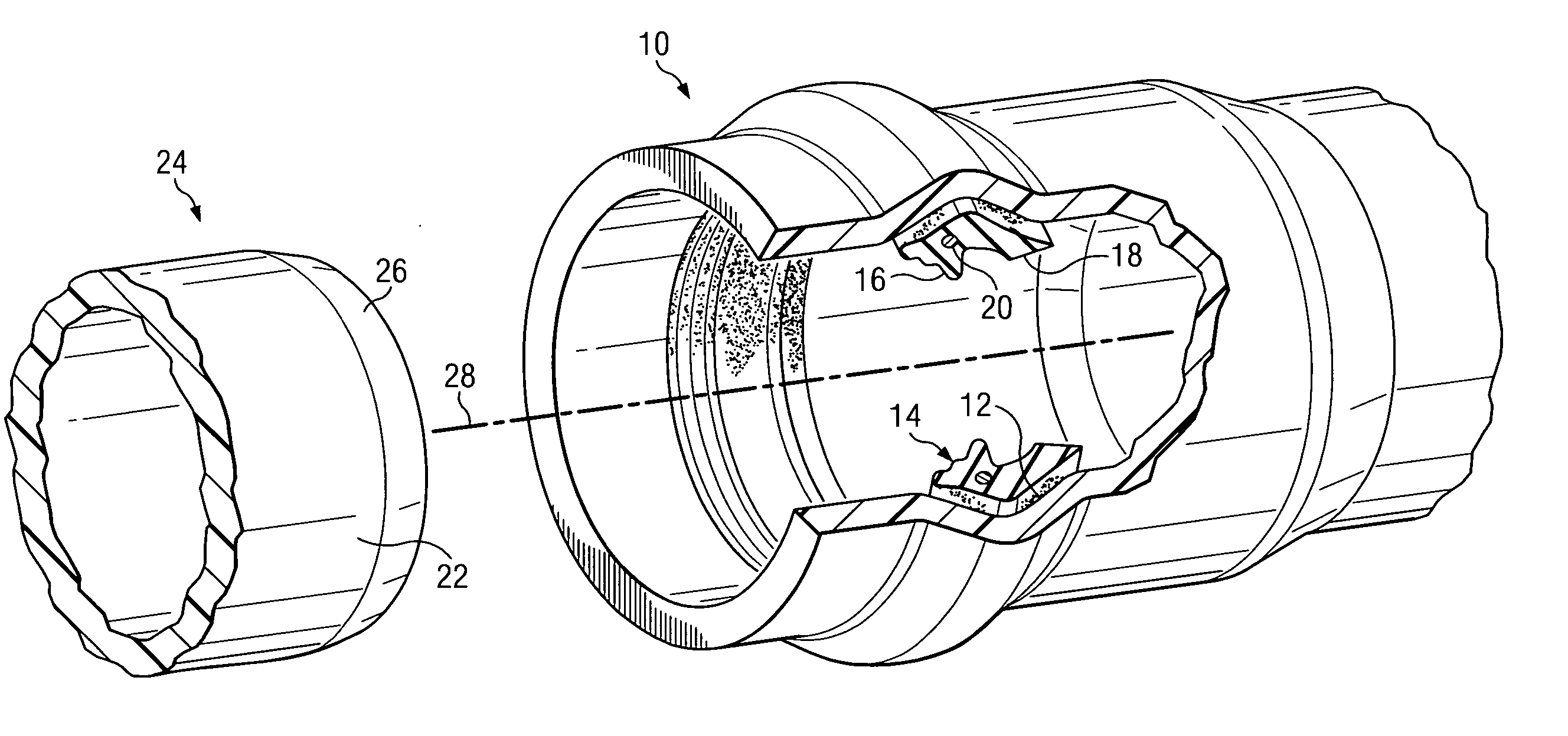
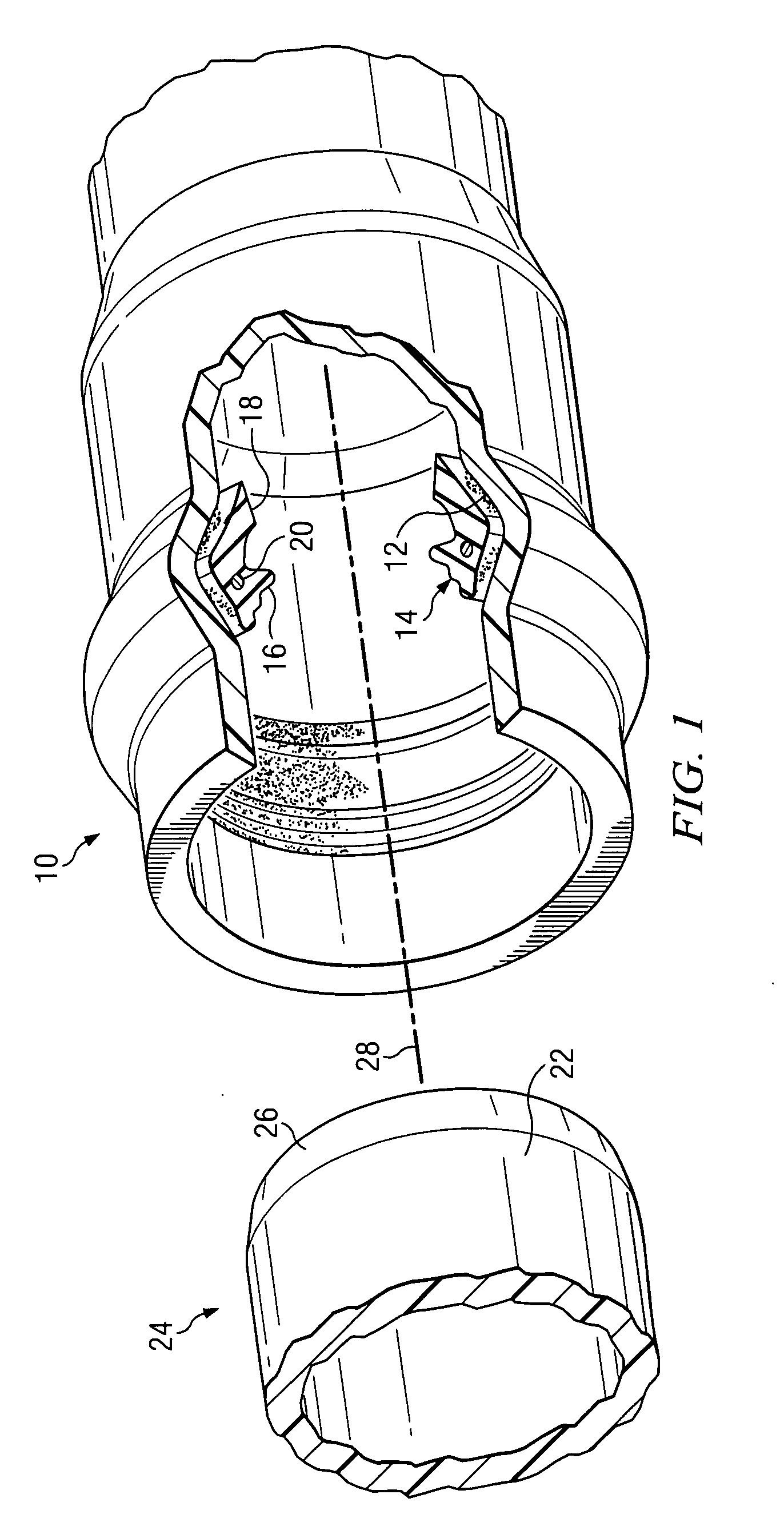
[0035] Turning to FIG. 1, there is shown an exploded view of a plastic pipe joint in which a belled female pipe end 10 is provided with an annular groove 12 for receiving an elastomeric sealing gasket 14. The annular sealing gasket 14 is a ring shaped member which, in cross section, has a compression seal region 16 and a trailing seal region 18. The gasket may be reinforced with a steel ring 20 which circumscribes the gasket body at one circumferential location. The sealing regions 16, 18 contact the exterior surface 22 of the mating male pipe section 24 upon assembly of the joint. During the assembly process, the male pipe end 24 travels to the left along the longitudinal axis 28 of the female, bell pipe end 10. Both of the pipe sections 10, 24 are formed of PVC. In the example illustrated in FIG. 1, the mating male pipe end 24 has a chamfered lip region 26. The sealing gasket is preferably made of a resilient elastomeric, thermoplastic material. For example, the sealing gasket may...


PUM

PropertyMeasurementUnit
angleaaaaaaaaaa
interface angleaaaaaaaaaa
distanceaaaaaaaaaa

Abstract

A method is shown for joining and sealing a female plastic pipe end having a belled end opening to a mating male plastic pipe end having an interior surface and an exterior surface. A sealing element is installed within a groove formed in the belled end of the female pipe section. The male pipe end is then inserted into the end opening of the female pipe end so that the elastomeric sealing gasket makes sealing contact with the exterior surface of the male pipe. A control mechanism controls the distance the male pipe travels longitudinally within the end opening of the female plastic pipe to prevent overinsertion of the male pipe within the female pipe opening.

Description

CROSS REFERENCE TO RELATED APPLICATIONS [0001] The present application claims priority from earlier filed provisional application Ser. No. 60 / 808,483, filed May 25, 2006, entitled “Method and Apparatus for Preventing Overinsertion in Plastic Pipe Systems,” by Guido Quesada and Shah Rahman.BACKGROUND OF THE INVENTION [0002] 1. Field of the Invention [0003] The present invention relates generally to the field of plastic pipe systems of the type used in the municipal water works industry and similar applications, and in particular, to methods and devices for preventing problems caused by overinsertion of the spigot pipe end within the mating belled pipe end in making a secure connection between two plastic pipes in a pipeline. [0004] 2. Description of the Related Art [0005] Pipes are commonly used for the conveyance of fluids under pressure, as in city water lines. They may also be used as free-flowing conduits running partly full, as in drains and sewers. Pipes for conveying water in ...

Claims


Application Information

Patent Timeline
Patent Type & Authority Applications(United States)
IPC IPC(8): F16L37/00
CPCF16L21/03F16L21/08F16L37/0925F16L47/12F16L47/08
Inventor QUESADA, GUIDORAHMAN, SHAHRIAR
Owner S & B TECHN PRODS
Learn More