
Composite structural member having an integrated electrical circuit

a structural member and integrated technology, applied in the direction of insulated conductors, cable connections, coupling devices, etc., can solve the problems of difficult or impractical connection of difficult or difficult to connect wires to the structural member, and high cost of construction

Active Publication Date: 2007-12-27
THE BOEING CO
View PDF25 Cites 18 Cited by
  • Summary
  • Abstract
  • Description
  • Claims
  • Application Information

AI Technical Summary

Problems solved by technology

In some cases, an extensive and complex network of wires may be required.
In some applications, however, it is difficult or impractical to connect the wires to the structural member.
For example, the structural member may not define any interior cavities through which the wires can be passed, and the environmental conditions outside the structural member may be harsh, for example, excessively warm or cold or subject to mechanical stress, moisture, or corrosive agents.
In addition, the weight and size of the wires may negatively affect the performance of the structural member.
Further, in applications where the structural member undergoes significant or repeated mechanical stress, the resulting strains in the wires can break the wires regardless of whether the wires are connected to the structural member.
The wires cannot be connected to the outside of the blade because of the external conditions, e.g., wind, moisture, and the like.
Further, the blade undergoes significant stress due to centripetal and aerodynamic forces.
In either case, the stress that results in the wires can break or fatigue the wires, rendering the electrical devices ineffective.

Method used


Image

  • Composite structural member having an integrated electrical circuit
  • Composite structural member having an integrated electrical circuit
  • Composite structural member having an integrated electrical circuit

Examples


Embodiment Construction

[0026] The present invention now will be described more fully hereinafter with reference to the accompanying drawings, in which some, but not all embodiments of the invention are shown. Indeed, this invention may be embodied in many different forms and should not be construed as limited to the embodiments set forth herein; rather, these embodiments are provided so that this disclosure will satisfy applicable legal requirements. Like numbers refer to like elements throughout.

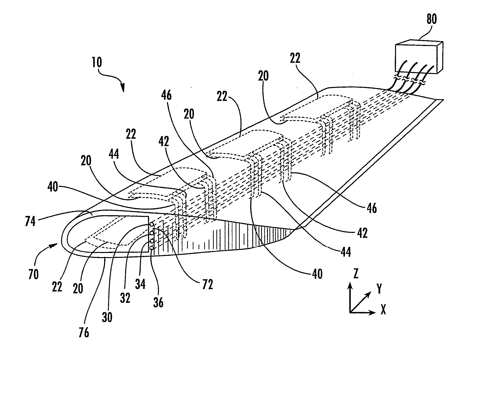
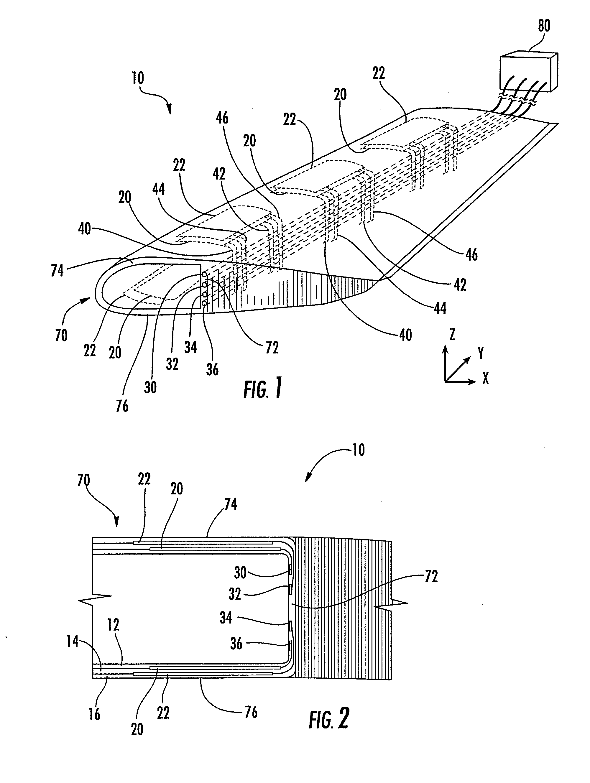
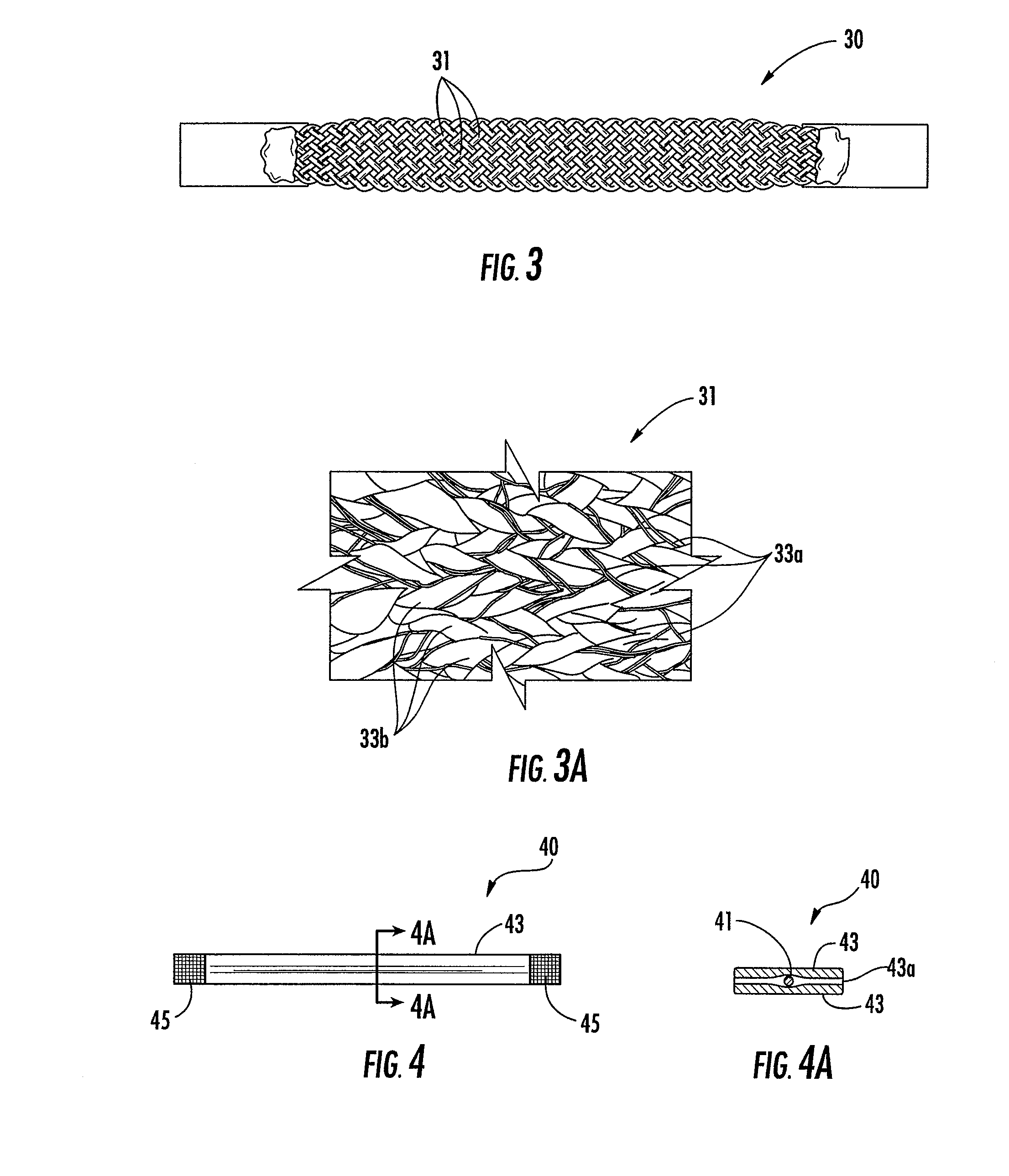
[0027] Referring now to the figures, and in particular to FIG. 1, there is shown a structural member 10 with a structurally integrated electrical circuit according to one embodiment of the present invention. The term “structural member” is not meant to be limiting, and the structural member 10 can be a single component or multiple assembled members, for example, building components or machinery. Further, the structural member 10 can be used in any type of structure including vehicles such as aerospace vehicles, ...


PUM

PropertyMeasurementUnit
temperatureaaaaaaaaaa
electrical poweraaaaaaaaaa
lengthaaaaaaaaaa

Abstract

A composite structural member with an integrated electrical circuit is provided. The structural member includes a plurality of layers of structural reinforcement material, and two or more electrical devices are disposed at least partially between the layers with an intermediate layer of the structural reinforcement material disposed between the electrical devices. At least one electrical bus is disposed in the structural member, and each electrical device is connected to the bus by a conductive electrode. Thus, the electrodes can extend through the intermediate layer of the structural reinforcement material to connect each of the electrical devices to one or more of the buses.

Description

CROSS REFERENCE TO RELATED APPLICATIONS [0001] This application is a divisional of U.S. patent application Ser. No. 10 / 848,703, filed May 19, 2004, which is hereby incorporated herein in its entirety by referenceFEDERALLY SPONSORED RESEARCH OR DEVELOPMENT [0002] This invention was made with government support under contract number NCC2-9019 awarded by the Rotorcraft Industry Technology Association, Inc. (RITA). The government may have certain rights in this invention.BACKGROUND OF THE INVENTION [0003] 1) Field of the Invention [0004] The present invention relates to a structural member with an integrated electrical circuit and, in particular, to a structurally integrated circuit including multiple electrical devices that are electrically connected by electrodes to one or more electrical buses. [0005] 2) Description of Related Art [0006] Electrical devices are often used in conjunction with a structural member. For example, electrical devices such as sensors and actuators can be embe...

Claims


Application Information

Patent Timeline
Patent Type & Authority Applications(United States)
IPC IPC(8): H01R13/66B29C35/02B29C70/68B29C70/86B29C70/88B64C27/473H01B7/00H05K1/03H05K1/16
CPCB29C35/0272Y10T29/49155B29C70/885B64C27/473B64C2027/7283H05K3/0058H05K3/103H05K3/281H05K2201/10151H05K2201/1028Y02T50/34Y10T29/49087Y10T428/24942Y10T29/49101Y10T29/49085Y10T29/49082Y10T29/49083Y10T29/49117Y10T29/49099B29C70/86Y02T50/30B29C70/681B29C70/685B29C70/882H01B7/0009H01B7/009
Inventor MARSHALL, JOSEPH A.WEEMS, DOUGLAS B.BUSSOM, RICHARD C.ANDERSON, DAVID M.
Owner THE BOEING CO
Learn More