
Display Device

a technology of display device and display screen, which is applied in the direction of static indicating device, dashboard fitting arrangement, instruments, etc., can solve the problems that the current display device is sometimes designed not to be able to display television, movies, etc. while the car is moving, and the suitable operation control desired by the user cannot be performed, so as to improve the safety, improve the operability and convenience, and improve the effect of safety

Inactive Publication Date: 2007-12-27
FUJITSU GENERAL LTD
View PDF13 Cites 53 Cited by
  • Summary
  • Abstract
  • Description
  • Claims
  • Application Information

AI Technical Summary

Benefits of technology

[0027] Therefore, the present invention has still another object the provision of a control system enabling suitable operation desired by the user to be performed in a state where individual display images for a plurality of viewing directions are displayed on the common screen of a display unit.
[0203] an operation limiting means for validating only an operation by the touch panel type operating means and invalidating an operation by the remote operating means when the valid operation setting condition judging means judges that the valid operation setting condition stands. When the valid operation setting condition stands, only an operation on the second display image by the remote operating means becomes valid. Due to this, it is possible to limit an operation on the first display image. For example, a valid operation setting condition is a state where the driver of a car should concentrate on driving and the valid operation setting condition stands. It is possible to invalidate an operation on the driver's seat use display image (first display image) and validate an operation on the passenger's seat use display image (second display image). Due to this, the driver can be kept from being distracted by operation of the remote operating means and safety during driving can be improved.

Problems solved by technology

Current display devices are therefore sometimes designed not to be able to display television, movies, etc. while the car is moving.
In other words, if this judgment cannot be suitably made, suitable operational control desired by the user can no longer be performed.

Method used


Image

  • Display Device
  • Display Device
  • Display Device

Examples


Embodiment Construction

[0297] Below, display devices according to embodiments of the present invention will be explained based on the drawings.

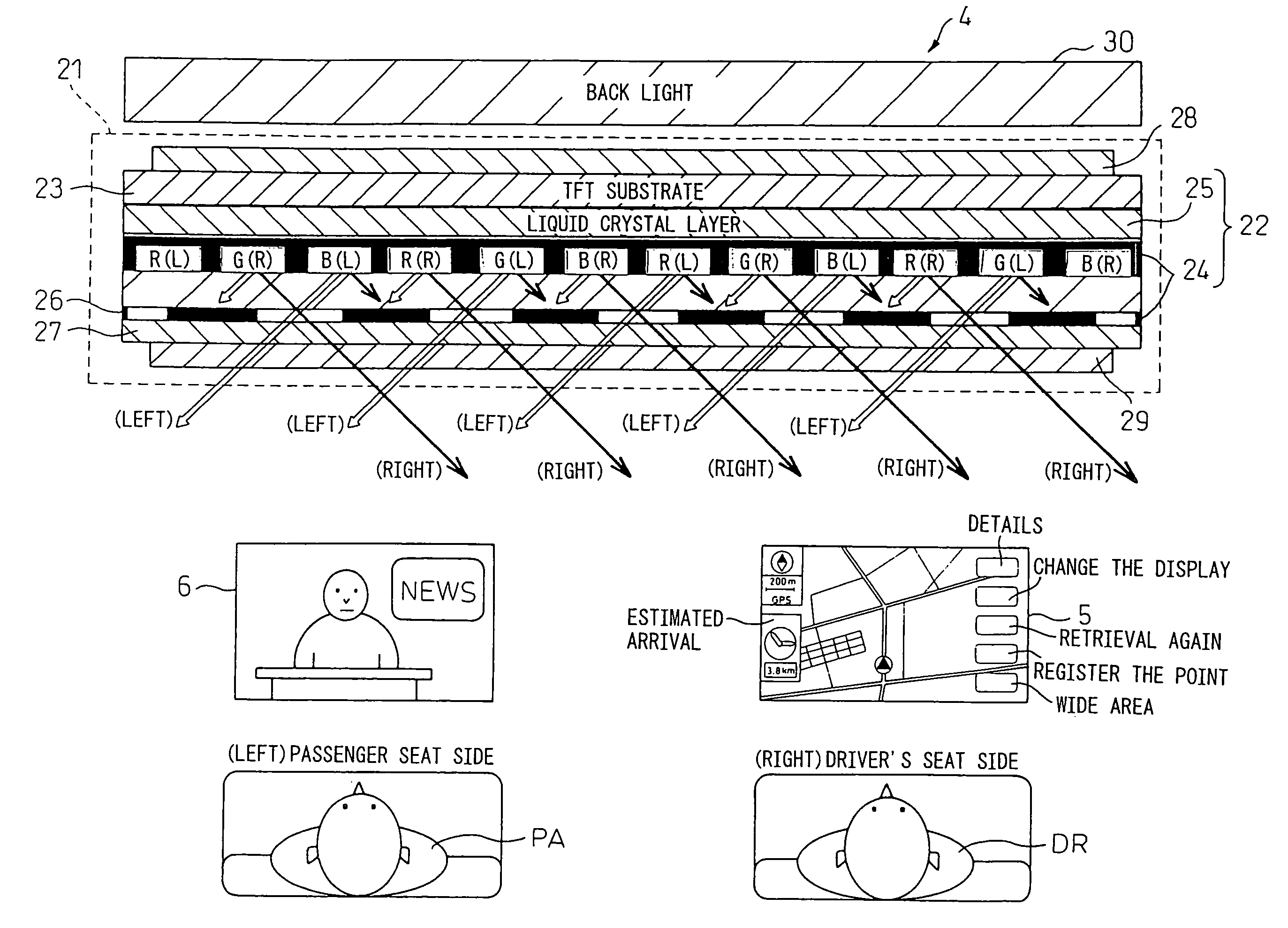
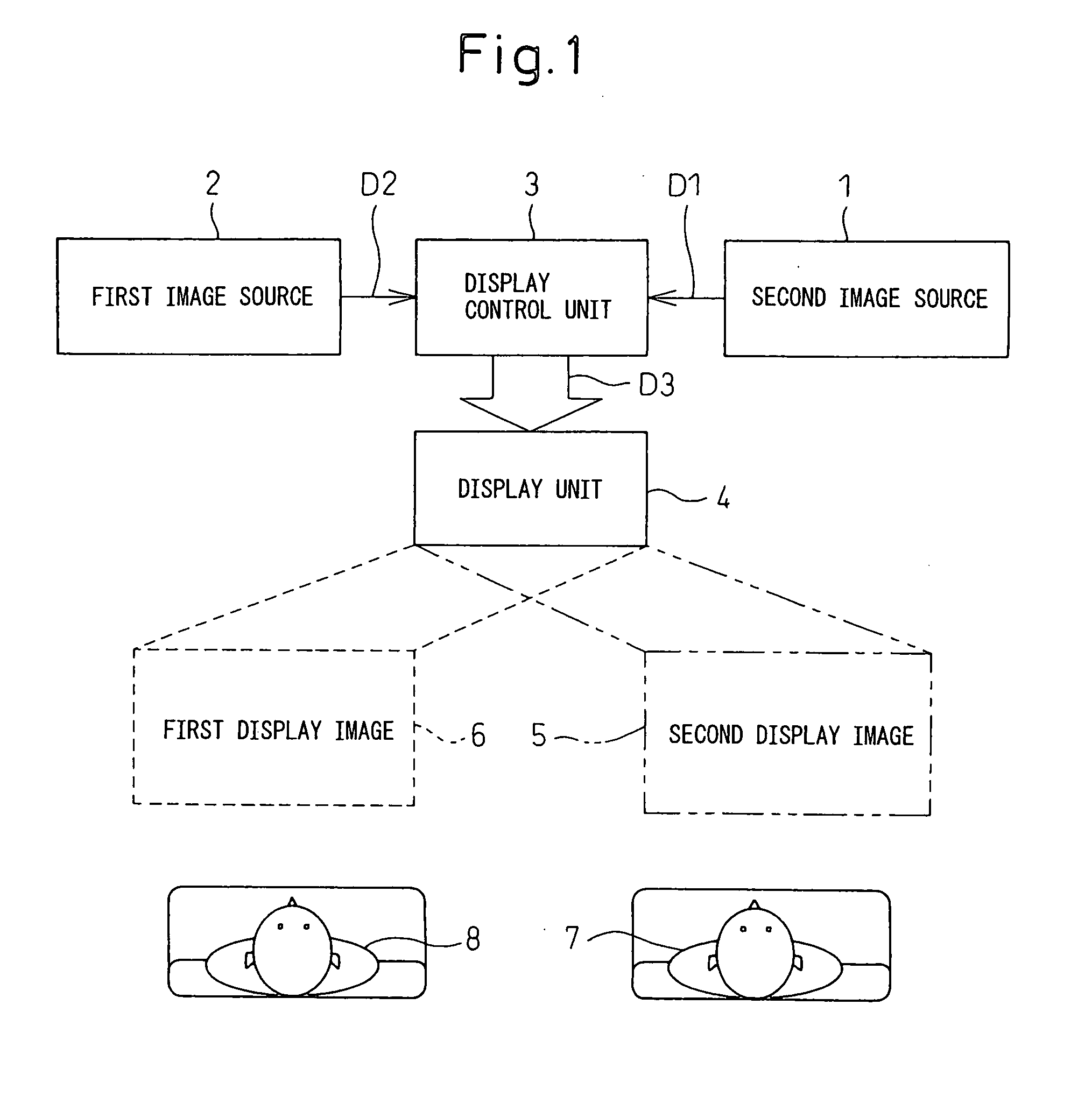
[0298]FIG. 1 is an explanatory view for explaining a function of displaying individual pictures for a plurality of viewing directions on the common screen in a display device. In the figure, 1 shows a first image source, while 2 shows a second image source. As the image source, for example, a DVD player, television receiver, navigation system, etc. may be mentioned.

[0299] First image data D1 obtained from the first image source 1 and second image data D2 obtained from the second image source 2 are supplied to a display control unit 3. These first image data D1 and second image data D2 are processed by the display control unit 3 so that the display unit 4 can display them substantially simultaneously, while the processed display data D3 is supplied to the display unit 4.

[0300] The display unit 4 will be explained in detail later, but as shown in FIG. 3(b) it is c...


PUM


Abstract

Even if a driver's seat use picture able to be seen from a driver and not able to be seen from a passenger's seat passenger and a passenger's seat use picture able to be seen from a passenger's seat passenger and not able to be seen from the driver are displayed on the common screen, suitable operational control desired by a user is realized. Means are provided for judging whether operations on operating switches 42DR to 47DR and 42PA to 47PA arranged so that an operating region on the display screen for the driver's seat use picture GDR and an operating region on the display screen for the passenger's seat use picture GPA overlap are from the driver's seat direction or from the passenger's seat direction and performing operational control for the picture able to be seen from that direction.

Description

FIELD OF THE INVENTION [0001] The present invention relates to a display device, more particularly relates to a display device for providing independent, different information to a plurality of viewers (users) substantially simultaneously on the common screen. BACKGROUND OF THE INVENTION [0002] While driving a car, a driver is prohibited from watching television, a movie, etc. Current display devices are therefore sometimes designed not to be able to display television, movies, etc. while the car is moving. For this reason, passengers other than the driver (for example, the passenger in the passenger's seat next to the driver) are also often unable to watch television or a movie in a moving car despite their watching television or a movie not being prohibited. [0003] On the other hand, in recent years, in car-mounted display devices, various technology has been proposed making the content of the display to the driver and the content of display to the passengers other than the driver...

Claims


Application Information

Patent Timeline
IPC IPC(8): G02B27/14G09G5/00
CPCB60K35/00B60K37/06B60K2350/901B60K2350/903B60R11/0235B60R2011/0282H04N13/0497G06F3/0418G06F3/0488G09G3/003H04N13/0409H04N13/0422H04N13/0456G06F3/0412H04N13/324H04N13/31H04N13/361H04N13/398G06F3/0421B60K35/10B60K35/656B60K35/654G09G3/36B60R11/02G09G3/20G02F1/133
Inventor WATANABE, SHINJIYASUDA, KATSUHIROMIYAZAWA, EIJIKAJIMOTO, NOBUAKIKOUJIMOTO, KENICHIHAMATANI, KIYOSHITAKEUCHI, TOMONORIFUKUDA, TAKAKOOOTANI, YOSHIHIDE
Owner FUJITSU GENERAL LTD
Learn More