Auxiliary Handle for a Hand-Held Power Tool

Inactive Publication Date: 2007-12-20
ATLAS COPCO ELECTRIC TOOLS
View PDF39 Cites 11 Cited by
  • Summary
  • Abstract
  • Description
  • Claims
  • Application Information

AI Technical Summary

Benefits of technology

[0006]It is an object of the present invention to further develop the auxiliary handle of the aforementioned kind in such a way that a safe and simple vibration-damped connection between the handle part and the attachment part is provided.
[0008]An auxiliary handle of a hand-held power tool is proposed in which the holding section and the securing section each are formed as a unitary part wherein the holding section surrounds with positive fit the securing section on all sides with play so as to form a damping space. The damping element fills out the damping space at least partially, preferably completely. The selected wording “surrounding on all sides” means that enclosure in all spatial direction is provided wherein a hermetic enclosure is possible but not necessary. The enclosure from all sides, on the one hand, provides a positive locking positional securing of the handle part relative to the attachment part. On the other hand, the damping element is secured captively and protected from external influences. The handle part cannot become detached from the attachment part even when the damping element is damaged. The unitary configuration of the holding section and of the securing section, respectively, improves the load capacity while reducing manufacturing and assembly costs. Since the damping element fills out the damping space, it is loaded as a whole when a relative damping movement occurs wherein the existing damping material in its totality is utilized for the damping action. In comparison to the prior art, a significantly more compact configuration is obtained while a high load capacity is provided; as a result of the reduced constructive space and the reduced weight, this contributes to improved handling of the power tool.
[0009]It can be expedient to produce the holding section, the securing section, and the damping element as individual parts wherein the damping element, for example, is fitted into the damping space or connected by an adhesive. In a preferred embodiment, the damping element, the holding section, and the securing section are formed as multi-component injection molded parts. With minimal manufacturing and assembly expenditure, an intimate connection between the three components is produced. The individual materials adhere to one another so that at the contact surfaces in addition to compressive stress also tensile stress and shearing stress can be transmitted. In this way, it is ensured that the existing damping material as a whole contributes to the damping action.
[0010]In a preferred embodiment, the securing section engages captively the holding section when the damping element is missing. Inasmuch as the damping element is damaged or even destroyed, the handle, even when the damping element is missing completely, cannot become detached from the power tool; this improves the operational safety of the power tool.
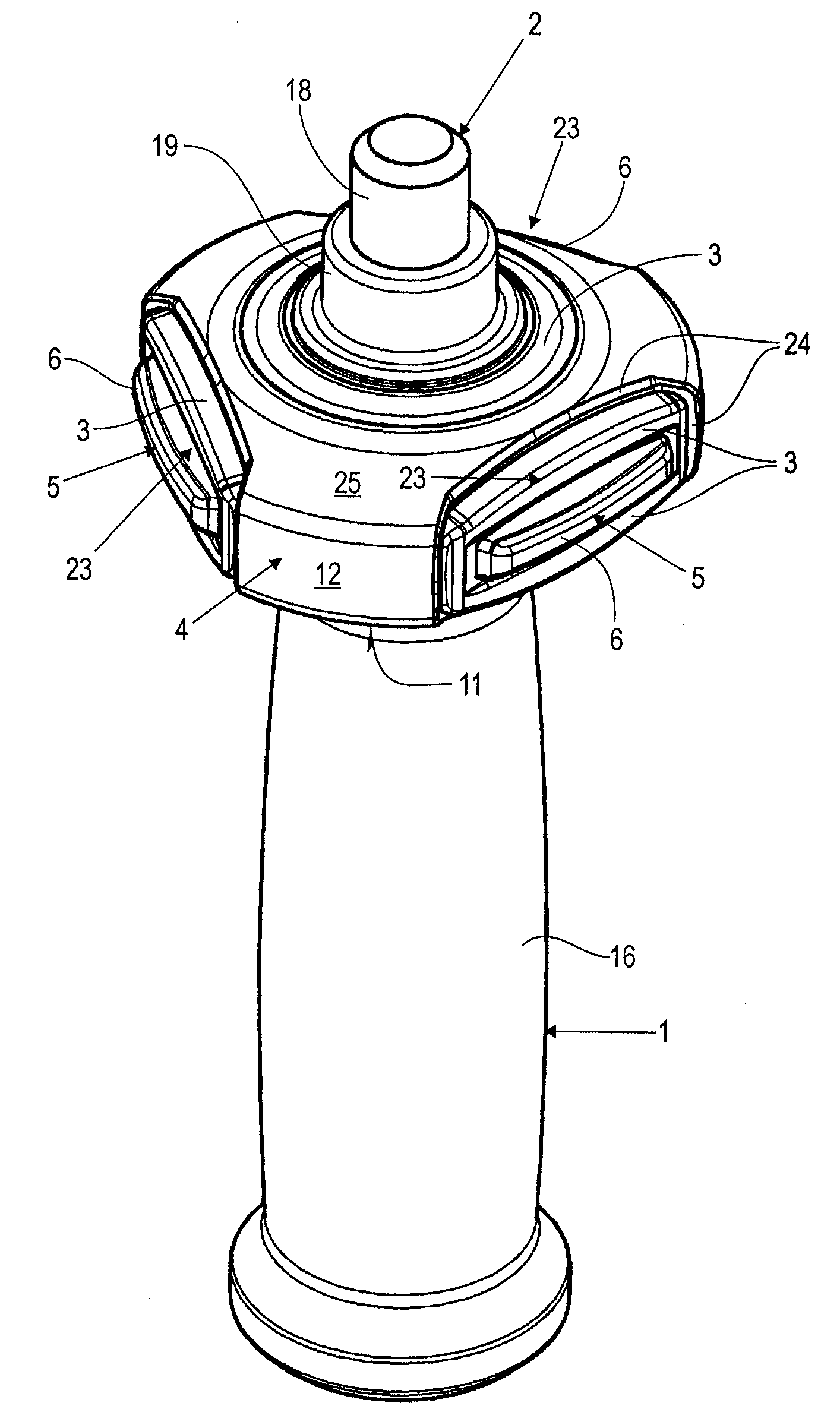
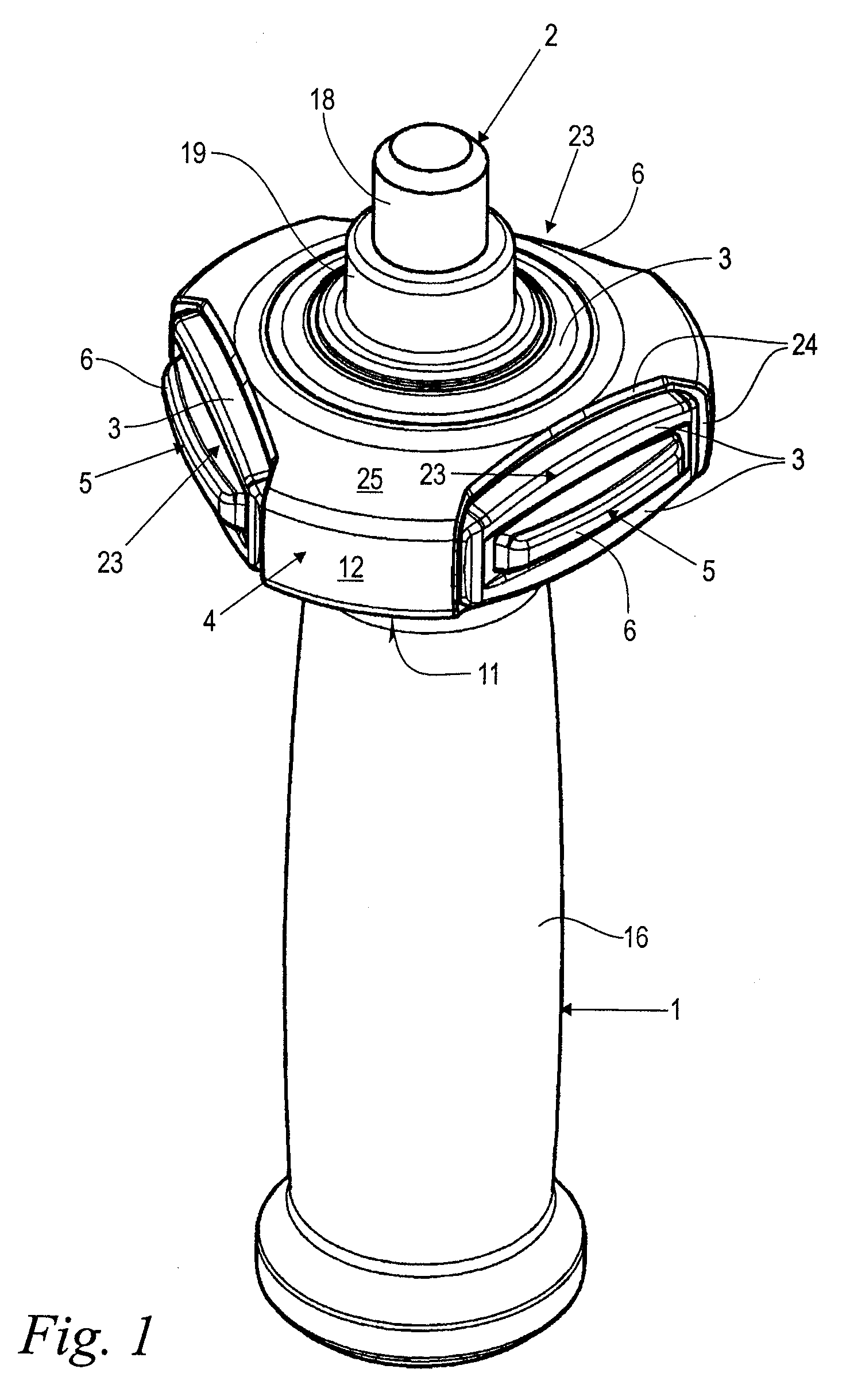
[0011]In an expedient embodiment, the safety section has at least two, and preferably three, securing projections that are spaced in the circumferential direction at a spacing from one another and project radially outwardly. The holding section has a circumferential wall that delimits the damping space in the radial direction wherein the circumferential wall has securing openings correlated with the securing projections. The securing projections engage the securing openings so that a spacing relative to the edges of the safety openings is provided on all sides. Expediently, the spacing between the securing projections and the edges of the securing openings is filled with the material of the damping element. A defined independently adjustable damping action can be obtained in all spatial degrees of freedom of the lateral and pivoting relative movement between handle part and power tool. The circumferential wall as well as the front wall and the back wall of the holding section delimit the lateral and also the pivoting degrees of freedom of movement. The interaction of the securing projections with the edges of the securing openings and the intermediately positioned material of the damping elements contribute moreover to the adjustment of the stiffness and damping behavior at relative pivoting and torsional movement. The damping material that is intermediately positioned in any direction provides that individual components, for example, the securing projections, impact on the holding section. The securing openings allow also a visual control of the damping elements so that damage, wear, and the like can be recognized in time.
[0016]In an expedient embodiment a constructive unit of the holding section and of a grip pipe of the handle part is of a unitary configuration. In this case, a highly loadable and still lightweight configuration is possible at further reduced manufacturing and assembly expenditure. Advantageously, the material of the elastic damping element is arranged at least partially, in particular unitarily, about the grip pipe and preferably at least partially about the holding section on the external side. Without additional manufacturing and assembly expenditure the surface feel (“grip”) of the auxiliary handle is improved. At the same time, the externally positioned material of the damping element also provides an impact and shock absorbing action with respect to external loads.

Problems solved by technology

The operation of the power tool results in vibrations that travel from the power tool, in particular through the auxiliary handle, into the hand or arm of the operator.
The arrangement of the additional securing element causes additional costs and additional weight.
The construction is complex and cost-intensive with regard to manufacture and assembly.
The arrangement of the large number of individual damping elements for supporting the main handle in all spatial degrees of freedom of movement require a large mounting space which, in the case of an auxiliary handle, limits the movability of the power tool.
An adaptation to different stiffness and damping properties for different degrees of freedom of movement is difficult.

Method used


Image

  • Auxiliary Handle for a Hand-Held Power Tool
  • Auxiliary Handle for a Hand-Held Power Tool
  • Auxiliary Handle for a Hand-Held Power Tool

Examples


Embodiment Construction

[0025]FIG. 1 shows in a perspective illustration an auxiliary handle according to the invention that is designed for use with a hand-held power tool, in particular, an angle grinder or cut-off machine, a buffing machine, a power drill or the like. The illustrated auxiliary handle comprises a handle part 1 that in operation is gripped by the hand of the operator. Further parts of the auxiliary handle are an attachment part 2 and an elastic damping element 3 with which the handle part 1 is attached in a vibration-damping way to the attachment part 2.

[0026]A screw 18 with thread projects from the attachment part 2 coaxially to the auxiliary handle 1 and is provided for screw-connecting the auxiliary handle to the power tool. In the usual operating position, the longitudinal axis of the auxiliary handle is radial to the longitudinal axis of the power tool and, depending on the application, can be oriented laterally, toward the top, downwardly, as well as in any intermediate position. Th...


PUM


Abstract

An auxiliary handle for a hand-held power tool has a handle part gripped by a hand of an operator and defining an axial direction. An attachment part with which the auxiliary handle is to be attached to a power tool is provided. An elastic damping element connects the handle part and the attachment part, wherein the handle part is secured to the attachment part by positive fit. A unitary holding section is connected to the handle part or the attachment part and a unitary securing section is connected to the attachment part or the handle part. The holding section surrounds with lateral play in all directions the securing section on all sides so that a damping space is generated between the securing section and the holding section. The damping element fills out the damping space at least partially.

Description

BACKGROUND OF THE INVENTION[0001]The invention relates to an auxiliary handle of a hand-held power tool, in particular, an angle grinder or cut-off machine, a buffing machine, a power drill, or the like. The auxiliary handle comprises a handle part to be gripped by the hand of the operator and an attachment part connected to the power tool, wherein the handle part is attached by means of an elastic damping element to the attachment part and is positive-lockingly secured to the attachment part.[0002]Hand-held power tools such as angle grinders or cut-off machines, buffing machines, power drills or the like have a main handle that is unitarily formed on or attached to the motor housing or the like. The power tool is gripped by the handle and guided by means of the handle. In addition to this handle, it may be expedient to provide an auxiliary handle for the second hand of the user. Such an auxiliary handle is detachably attached, for example, to the gear housing of the power tool. Whe...

Claims


Application Information

Patent Timeline
IPC IPC(8): B25D17/24B25D17/00
CPCB25F5/026B25F5/006
Inventor KUMPF, RAINERROBIEU, THOMAS
Owner ATLAS COPCO ELECTRIC TOOLS
Why Eureka
Try Eureka