
Synthetic Nervous System for Robotics

a robotics and nervous system technology, applied in the field of analog circuitry, can solve the problems of limiting feedback control beyond the power consumption of motors, complex circuits using custom silicon and digital signal processors, and high cost, and achieve the effects of minimizing circuitry, maximizing processing power, and minimizing circuitry

Inactive Publication Date: 2007-12-13
NEW SCHOOL TECH
View PDF11 Cites 9 Cited by
  • Summary
  • Abstract
  • Description
  • Claims
  • Application Information

AI Technical Summary

Benefits of technology

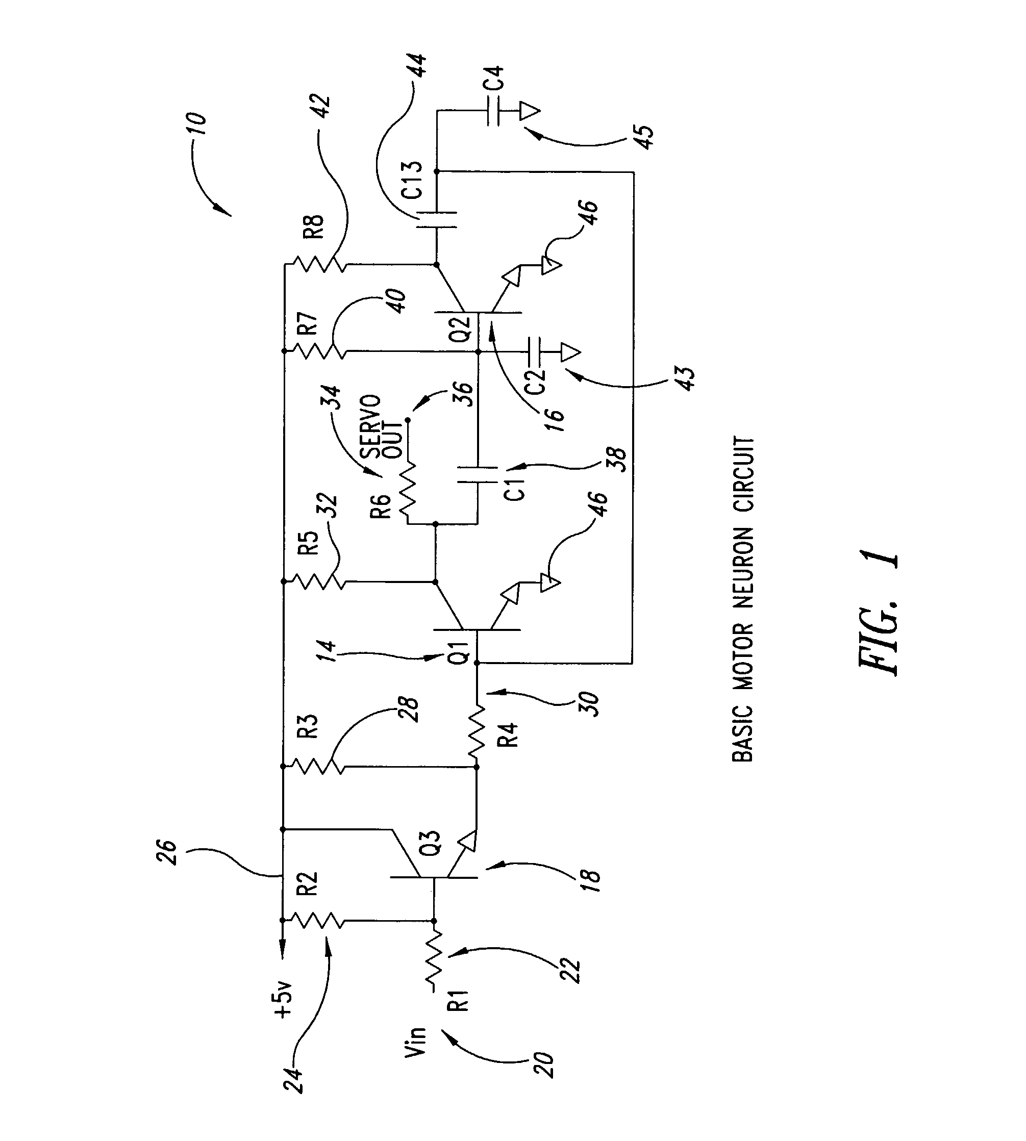
[0007] The disclosed embodiments of the invention are directed to robotic systems, and particularly to control circuits for robotic systems utilizing a basic motor neuron circuit that synthesizes all forms of limbed, finned, and undulating robotic locomotion. In one embodiment, an oscillating infinite state machine approach is used wherein analog circuits utilizing off-the-shelf servo motors, particularly those used in radio controlled aircraft and model cars, provide a simplified and cost-effective method for controlling locomotion and other robotic movement.
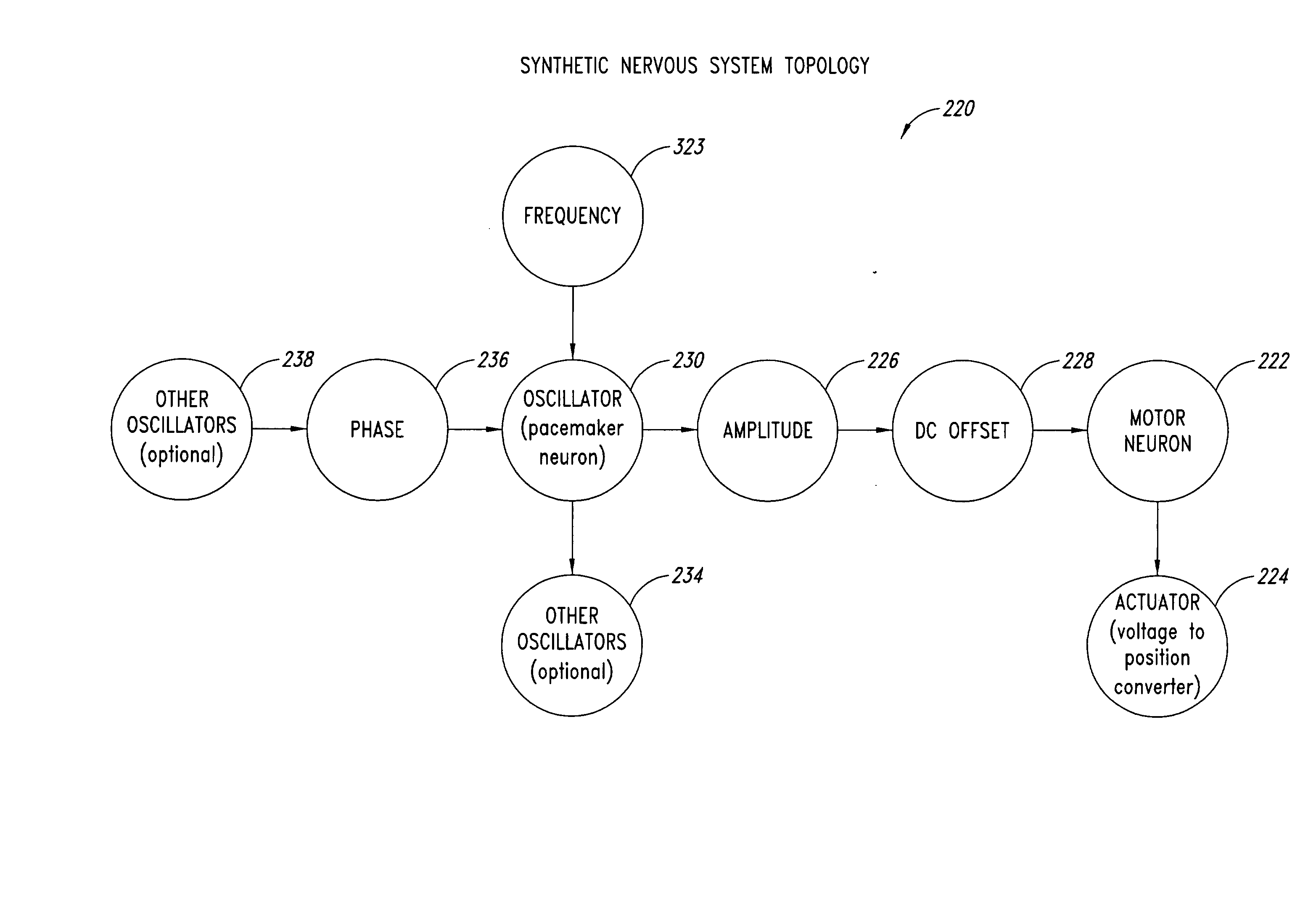
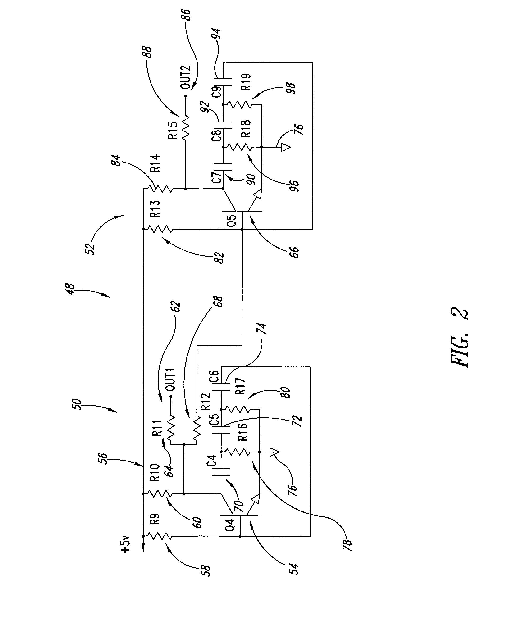
[0014] In accordance with yet a further embodiment of the invention, a synthetic nervous system for robotic applications having a control circuit and servo actuators using continuously variable analog voltages to mimic natural bio-neural processes is provided that includes a central pattern generator utilizing periodic, quasi-periodic, or chaotic oscillators or phase shifters, or a combination thereof, along with a basic motor neuron circuit. Ideally the system enables multiple motor neurons to coordinate their behavior to enable such things as walking, swimming, flapping, crawling, and the like. Sensors interfaced to the control circuit provide a wide range of adaptive behavior such as following light, avoiding an obstacle, and shifting a balance point. Overlapping or concurrent behavior can provide complex behaviors with minimal circuitry.
[0015] As will be readily appreciated from the foregoing, the approach of the present invention is fundamentally different from prior designs. Some contemporary systems use an integrate-and-fire design to robotics locomotion control using an adaptive ring oscillator while the present invention uses simple phased, coupled continuously variable analog logic and oscillators implemented as oscillating infinite state machines that can be modulated in frequency, phase, amplitude, and DC offset. These oscillators are used as computational elements capable of maximizing processing power while minimizing circuitry.

Problems solved by technology

This research and its resulting applications tends to be not only complex but also expensive.
Very complex circuits using custom silicon and digital signal processors have been created to simulate how a natural central processing generator and nervous system work.
The device of Tilden suffers from several disadvantages, one of which is that the actuated limb has no way of detecting where it is in its phase space, and hence it limits feedback control beyond motor power consumption.
In addition, Tilden utilizes Schmidt triggers in the central pattern oscillator that fire at one voltage and reset at a lower voltage to give a digital output, thus failing to take full advantage of the benefits of analog circuitry.

Method used


Image

  • Synthetic Nervous System for Robotics
  • Synthetic Nervous System for Robotics
  • Synthetic Nervous System for Robotics

Examples


Embodiment Construction

[0038]FIG. 1 is a circuit diagram of a basic motor neuron circuit 10 formed in accordance with one embodiment of the invention. This circuit is configured as a waveform generator for use with commercially available model-hobbyist type servos. The circuit 10 includes a rectangular wave multi-vibrator circuit formed of a first transistor (Q1) 14 and a second transistor (Q2) 16. A third transistor (Q3) 18 is configured to operate as a voltage-controlled resistor and is coupled between an input 20 (Vin) and a control terminal or base of the first transistor 14. A first resistor 22 (R1) is coupled between the input 20 and the control terminal or base of the third transistor 18, and a second resistor 24 (R2) is coupled between the control terminal or base of the third transistor 18 and a voltage source 26, which is preferably set at 5 volts for this application. The second resistor 24 provides a bias to the third transistor 18 so that it operates in the linear region and, functionally, as...


PUM


Abstract

A synthetic nervous system (10) capable of rudimental learning and self-organization for robotic applications having a control circuit (190) and servo actuators (224) using oscillating continuously variable analog voltages to mimic natural bio-neural processes. Simple oscillators (1-8) capable of being modulated in frequency, phase, amplitude, and DC offset act as analog processing elements or oscillating infinite state machines. A central pattern generator (140) utilizing periodic, quasi-periodic, or chaotic oscillators or phase shifters, or a combination thereof, along with a basic motor neuron circuit (314) enables multiple servos to coordinate their behavior to enable bio-inspired locomotion such as walking, swimming, flapping, crawling, and the like. Sensors (200) interfaced to the control circuit (190) provide a wide range of adaptive behavior such as following a light source, avoiding an obstacle, and shifting balance point. Overlapping or concurrent sensor input can provide complex behavior with minimal circuitry.

Description

BACKGROUND OF THE INVENTION [0001] 1. Field of the Invention [0002] The present invention is directed to robotic control systems and, more particularly, to analog circuitry that simulates natural neurons, including a central pattern generator utilizing the multiple domains of frequency, phase, amplitude, and DC offset, and to a continuously variable analog synthetic nervous system. [0003] 2. Description of the Related Art [0004] Robotic designs attempt to simulate the movement patterns of animals. With the exception of some lower invertebrates, animals have a nervous network that utilizes a central pattern generator to coordinate and synchronize the movements of their muscles. The central pattern generator has a pacemaker neuron functioning as a simple oscillator that does not require an input. The pacemaker neuron, when combined with a phase shifting network or interacting pacemaker neurons, causes the generation of an oscillating signal that is received at the muscle tissue throug...

Claims


Application Information

Patent Timeline
Patent Type & Authority Applications(United States)
IPC IPC(8): B25J9/16
CPCG06N3/0635B25J9/161G06N3/065
Inventor JENNER, THOMAS W. JR.
Owner NEW SCHOOL TECH
Learn More