Induction Sensor
a technology of induction sensor and sensor, which is applied in the direction of pulse technique, non-mechanical valve, instruments, etc., can solve the problems of small measurement resolution, low voltage differential, circuits adding much complexity for little improvement in performance, etc., and achieve the effect of improving performan
- Summary
- Abstract
- Description
- Claims
- Application Information
AI Technical Summary
Benefits of technology
Problems solved by technology
Method used
Image
Examples
Embodiment Construction
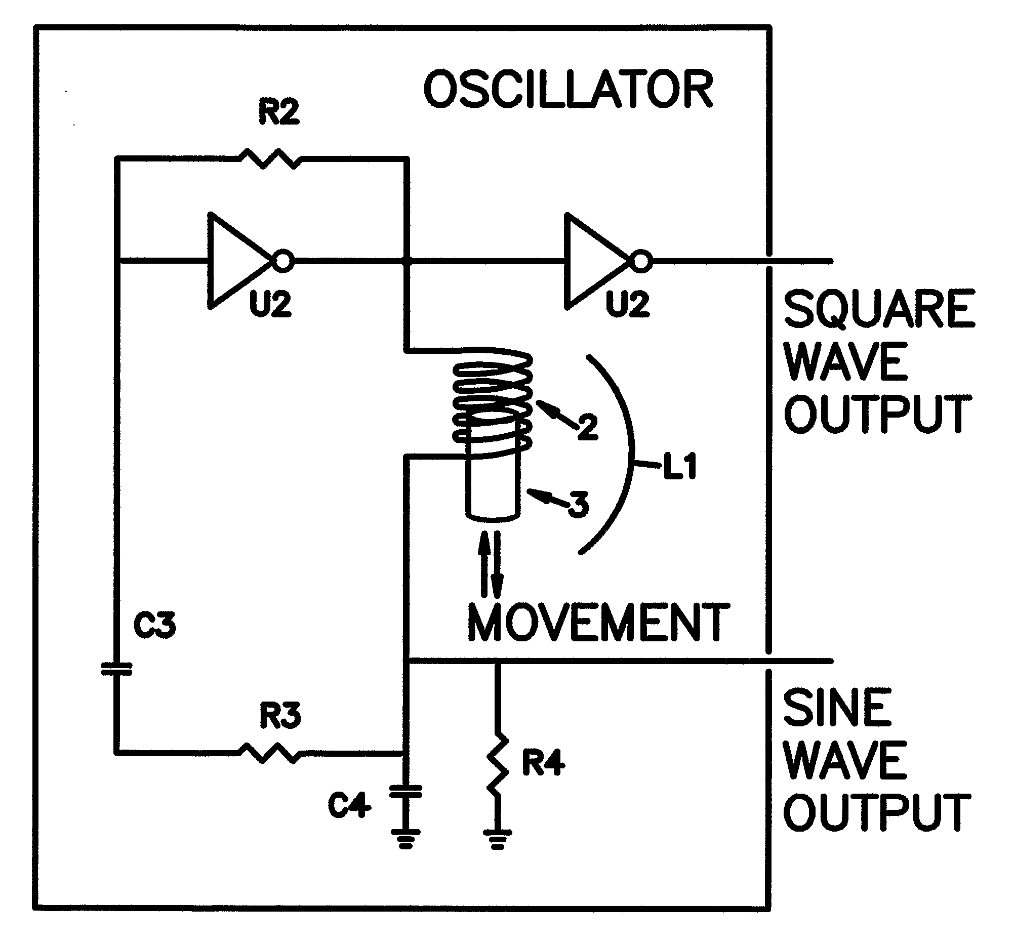
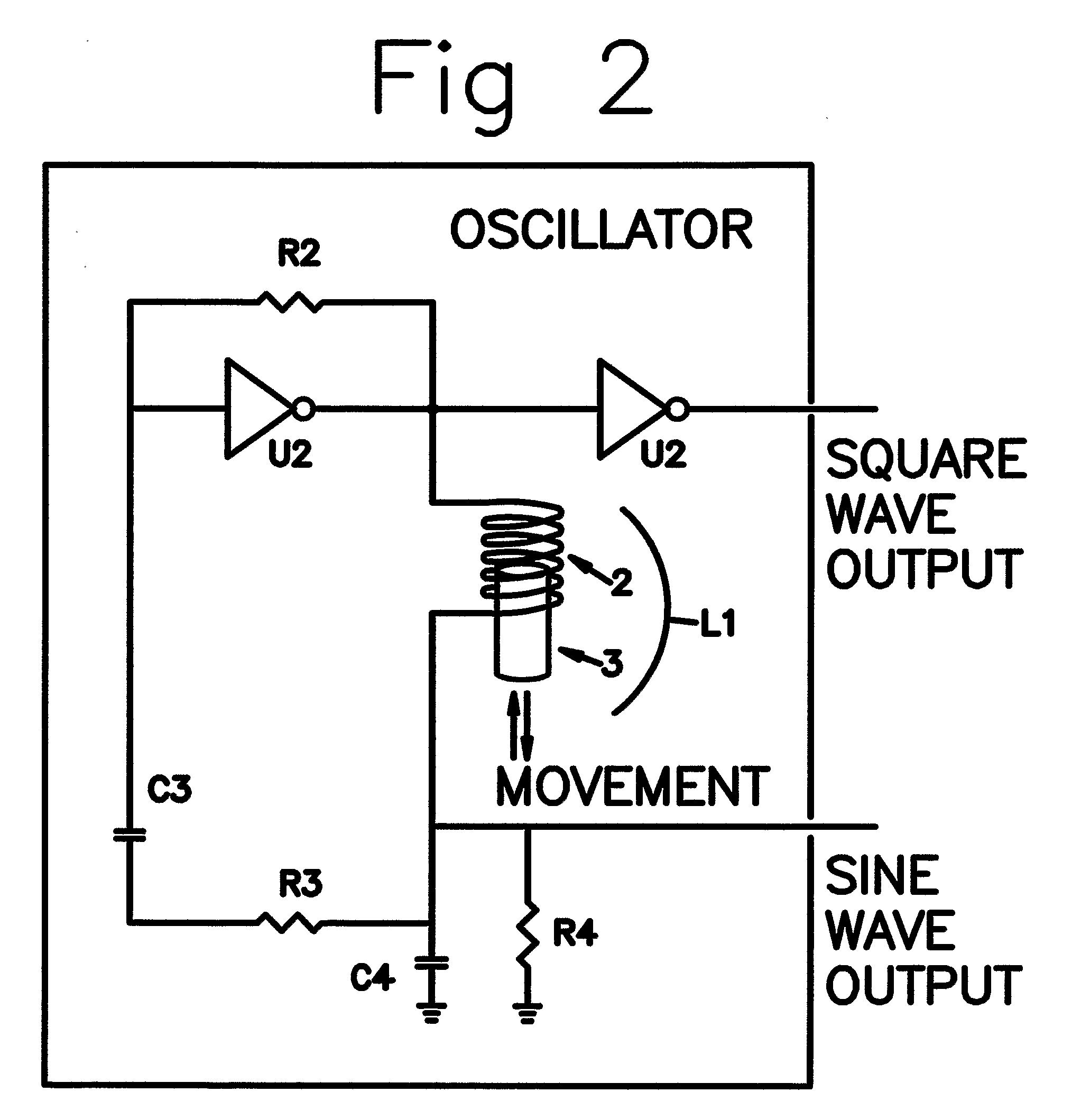
[0063]FIG. 2 shows the basic circuit of the present invention. The circuit is a tuned oscillator circuit. The tuned oscillator circuit is comprised of an amplifier (U2) and two reactive components, an inductor L1 and a capacitor C4. L1 and C4 are in series connection with C4 connected to ground (return) and L1 connected to the output of the amplifier U2. The frequency of the oscillator is: F=12πLC
[0064] The amplifier U2 shown in FIG. 2 is a high speed CMOS hex inverter. The resistor R2 is used to bias the input of the amplifier to compensate for the leakage current. The resistor R3 and capacitor C3 provide the feedback path. The oscillator is AC coupled by capacitor C3 so that there is no DC voltage path through the oscillator. A transistor amplifier or operational amp will also work in place of hex inverter U2. The inductor L1 is the coil in the sensors disclosed in this paper. Two signals can be generated from the oscillator for use as output. One signal is a square wave the ot...
PUM
 Abstract
Description
Claims
Application Information
 - R&D
- Intellectual Property
- Life Sciences
- Materials
- Tech Scout
- Unparalleled Data Quality
- Higher Quality Content
- 60% Fewer Hallucinations
Browse by: Latest US Patents, China's latest patents, Technical Efficacy Thesaurus, Application Domain, Technology Topic, Popular Technical Reports.
© 2025 PatSnap. All rights reserved.Legal|Privacy policy|Modern Slavery Act Transparency Statement|Sitemap|About US| Contact US: help@patsnap.com


