Detectors and actuating devices incorporating same

Inactive Publication Date: 2007-12-06
HONG KONG APPLIED SCI & TECH RES INST
View PDF14 Cites 0 Cited by
  • Summary
  • Abstract
  • Description
  • Claims
  • Application Information

AI Technical Summary

Benefits of technology

[0005]An optical detection arrangement of this invention provides a flexible optical detection means in which a prescribed location for actuation triggering can be adjusted. For example, the prescribed location can be adjusted to be nearer or further away from the optical detector by varying the spatial relationship between the optical detector and the optical collector. This arrangement facilitates a non-contact actuation of devices which would otherwise require finger contact operation.
[0006]In a preferred embodiment, the optical detector is a module with the optical source and the optical detector disposed within an enclosure. More particularly, the optical source is arranged for emitting a collimated beam out of the enclosure and towards the prescribed location, the prescribed location is outside the enclosure, the optical collector forms a light collecting window intermediate the prescribed location and the detector and is adapted for forwarding the collimated beam after being scattered by said object to said optical collector. The use of a collimated beam enhances positioning accuracy which is especially important for a high-density switch array. A modular design of the optical detector facilitates flexible deployment for multiple-switch applications which are beneficial for many practical purposes.
[0008]In one preferred embodiment, the optical source and the optical detector are disposed within an enclosure, said optical source is arranged for emitting a collimated beam out of said enclosure and said prescribed location is outside the enclosure; and wherein the optical collector forms a light collecting window intermediate said prescribed location and said detector and being for forwarding the collimated beam after being scattered by said object to said optical collector. The use of a collimated beam would enhance positioning accuracy while making the detector less prone to external and / or adverse stray light interference.
[0011]Preferably, said optical source is adapted for emitting a laser beam towards said prescribed location for subsequent scattering by said object towards said optical collector. As a convenient example, said optical source may comprise a modulated laser transmitter. More specifically, the laser transmitter may comprise a VCSEL laser emitter. The VCSEL laser may further comprise an optical feedback loop for stabilization of the laser transmitter. The use of a laser or other coherent light source will operate to mitigate adverse influence, for example, mitigates stray light interference and therefore enhances spatial accuracy.
[0012]In a preferred embodiment, said optical detector comprises a plurality of photo-detecting cells, outputs of the photo-detecting cells are compared for determining the presence of an object at the prescribed location. Preferably, outputs of said plurality of photo-detecting cells are differentially compared. The use of differential outputs further enhances measurement accuracy since common mode noise will be substantially reduced. More specifically, the detector further comprises decision circuitry for differentially comparing outputs of the photo-detecting cells.
[0015]To be more user friendly, each object detector is arranged for emitting a visual acknowledgement signal when an object is detected as being present at said prescribed location of that object detector. Preferably, each of the object detectors is adapted for detecting the presence of a finger at the prescribed location of that detector for non-contact actuation operation. This facilitates a convenient non-contact actuation of control buttons.

Problems solved by technology

With the increasing concern of health risk, for example, contraction of infectious diseases, such as SARS (Severe Acute Respiratory Syndrome), atypical pneumonia, avian flu or other contagious disease due to finger contact, operation of public appliances using finger contact is less desirable.

Method used


Image

  • Detectors and actuating devices incorporating same
  • Detectors and actuating devices incorporating same
  • Detectors and actuating devices incorporating same

Examples


Embodiment Construction

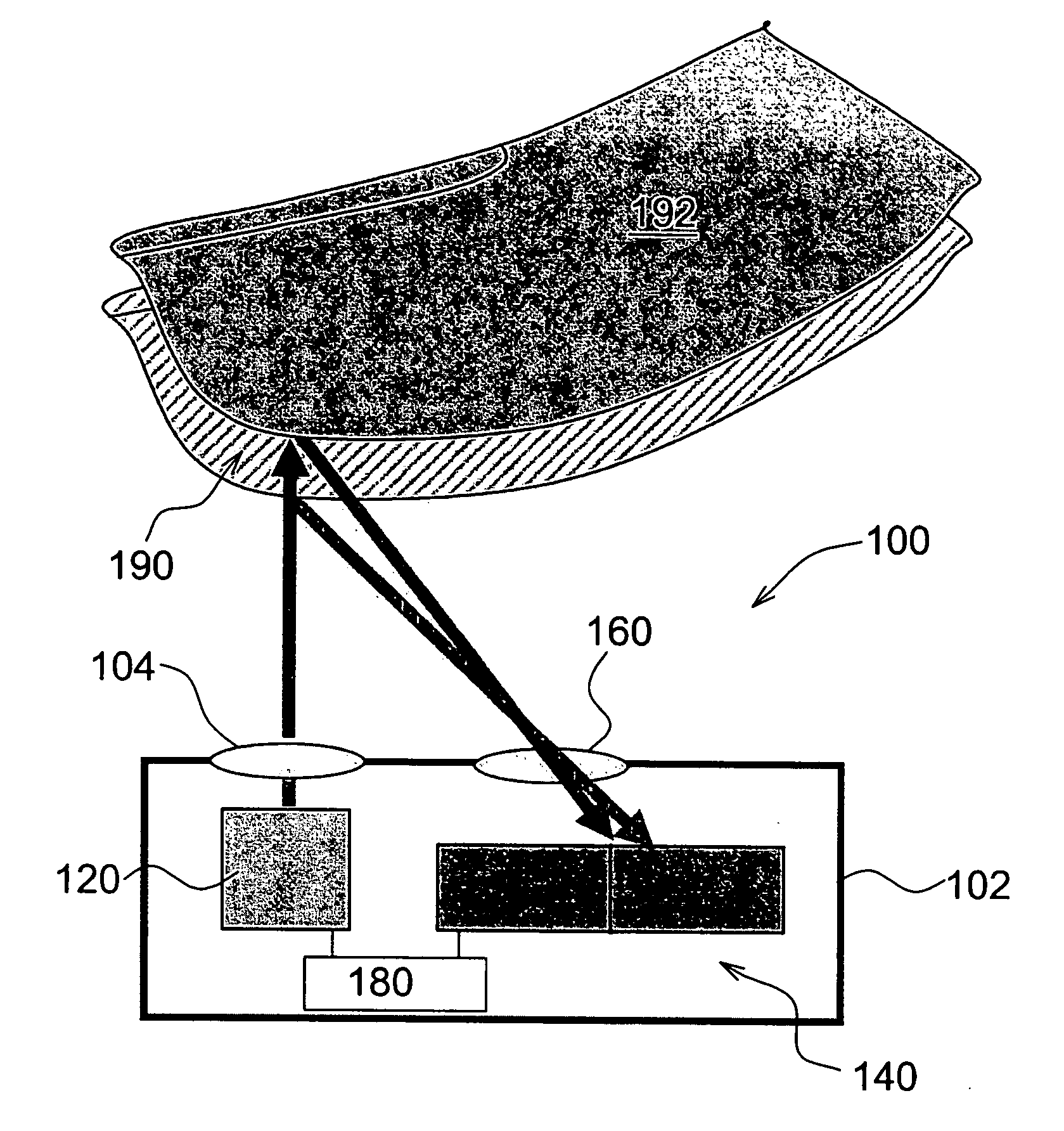
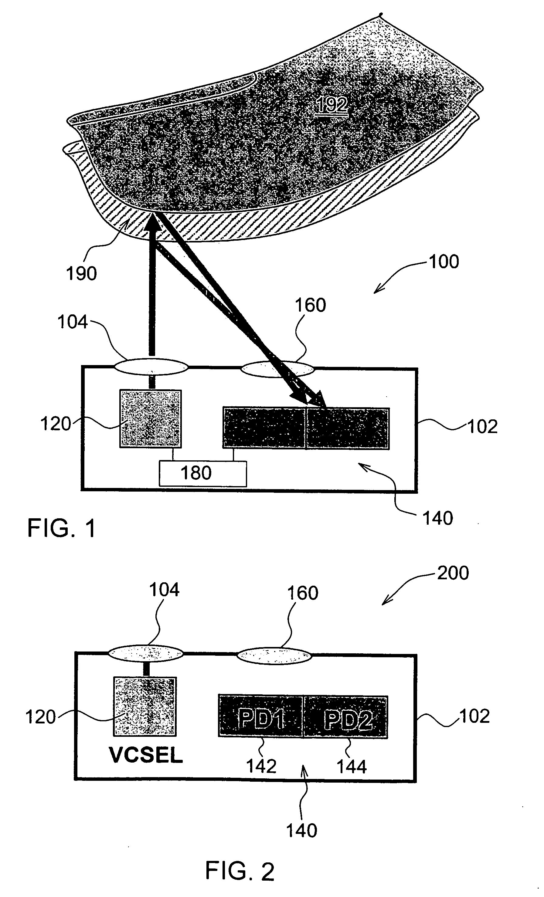
[0027]Referring to FIG. 1, there is shown an optical detector for detecting the presence of an object at a prescribed location. The optical detector 100 comprises an optical source 120, an optical detector 140, an optical collector 160 and control circuitry 180. The optical source is arranged for emitting a collimated optical beam, such as a laser beam, towards a prescribed location 190. More particularly, the optical detector is arranged for detecting optical signals emitted by the optical source. The optical collector is arranged for collecting optical beams scattered by an object 192 when located at the prescribed location 190 and for forwarding the optical beams to the optical detector for optical detection. The control circuitry 180 is provided for monitoring output of the optical detector and for determining the presence or absence of an object at the prescribed location by monitoring the output of the optical detector. In addition, the control circuitry also generates a contr...


PUM


Abstract

A detector for detecting the presence of an object at a prescribed location, the detector comprising:—an optical source arranged for emitting a collimated optical beam towards the prescribed location,an optical detector for detecting optical signals emitted by said optical source,an optical collector arranged for collecting optical beams scattered by an object located at the prescribed location and for forwarding said optical beams to said optical detector for optical detection; andcontrol circuitry for monitoring output of said optical detector and for determining the presence or absence of an object at said prescribed location by monitoring said output.

Description

FIELD OF THE INVENTION[0001]This invention relates to detectors and, more particularly, to an optical detector for detecting the presence of an object at a location by optical means. This invention also relates to an actuation device incorporating an optical detector.BACKGROUND OF THE INVENTION[0002]Many machines or apparatus are equipped with key-pad type actuation devices for human control and interaction. For example, ATMs (automatic teller machines) and lifts comprise a key-pad type actuation device for a user to operate the machine. A high precision numerical control cutting machine, such a CNC machine, is equipped with a keypad-type actuation device for input of control parameters. Typically, an actuation device is finger operated so that upon detection of a sequence of key movements, for example, a sequence of key depressions, the commands input by a user can be recognised.[0003]With the increasing concern of health risk, for example, contraction of infectious diseases, such ...

Claims


Application Information

Patent Timeline
IPC IPC(8): G06M7/00
CPCG01D5/34G01D5/30G01D2205/40
Inventor WIPIEJEWSKI, TORSTEN
Owner HONG KONG APPLIED SCI & TECH RES INST
Why Eureka
Try Eureka