
Well plate

a technology of well plates and plates, applied in the field of well plates, can solve the problems of significant cost, and achieve the effects of high or low cost, good optical quality of the base, and excellent performance characteristics

Inactive Publication Date: 2007-11-29
GENETIX LTD
View PDF6 Cites 56 Cited by
  • Summary
  • Abstract
  • Description
  • Claims
  • Application Information

AI Technical Summary

Benefits of technology

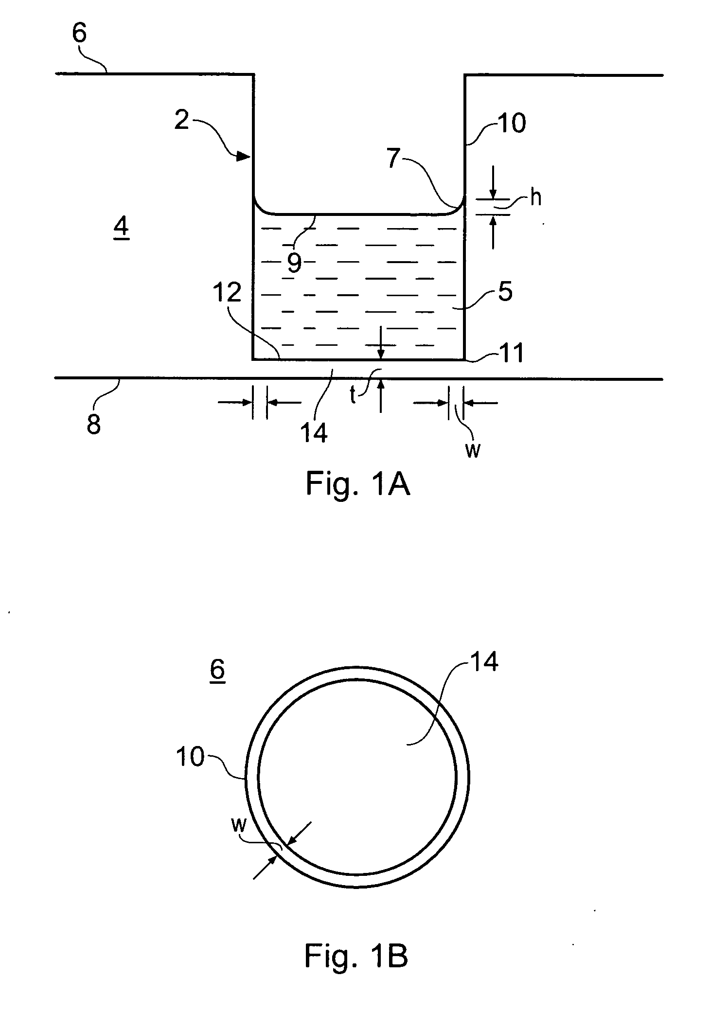
[0017]With a contact angle of precisely 90 degrees, the meniscus height will be zero. In reality, the benefit of the invention can be gained by sufficiently reducing the meniscus formation so that the undesirable optical and / or biological effects of interest discussed above are substantially reduced or avoided. For example, if the main aim is to ensure that phase contrast microscopy will be able to image across the full width of each well, then it will be sufficient so long as the height of the meniscus is reduced to below about a ½ wavelength of the light being used, typically to less than about 200-350 nm for visible microscopy, more preferably to below 1 / 10 wavelength, e.g. 40-70 nm.
[0044]A still further aspect of the invention is a method of cell counting and / or confluence detection, in which cells are cultured in a well plate of non-unitary construction having at least one well, each well being defined by a side wall and a base, wherein the well plate is constructed from a first part defining the side wall of each well and a second part defining the base of each wall, wherein the base has a surface energy that is lower than the side wall surface energy to promote preferential attachment of cells to the base relative to the side wall, so that cells substantially grow in a single plane defined by the base. This assists imaging, since all cells will lie in a common focal plane of the imaging apparatus used to capture the images used for image processing to count and / or measure confluence of the cells. Moreover, it also assists counting, since cells will not overlap each other, as viewed in the vertical direction, which makes the image processing more difficult.

Problems solved by technology

Furthermore, small volume wells may be necessary or desirable owing to the costs associated with reagents, some of which are significantly expensive.

Method used


Image

  • Well plate
  • Well plate
  • Well plate

Examples


Embodiment Construction

[0052]Before describing a well plate embodying the invention, some relevant general background regarding meniscus formation is summarized.

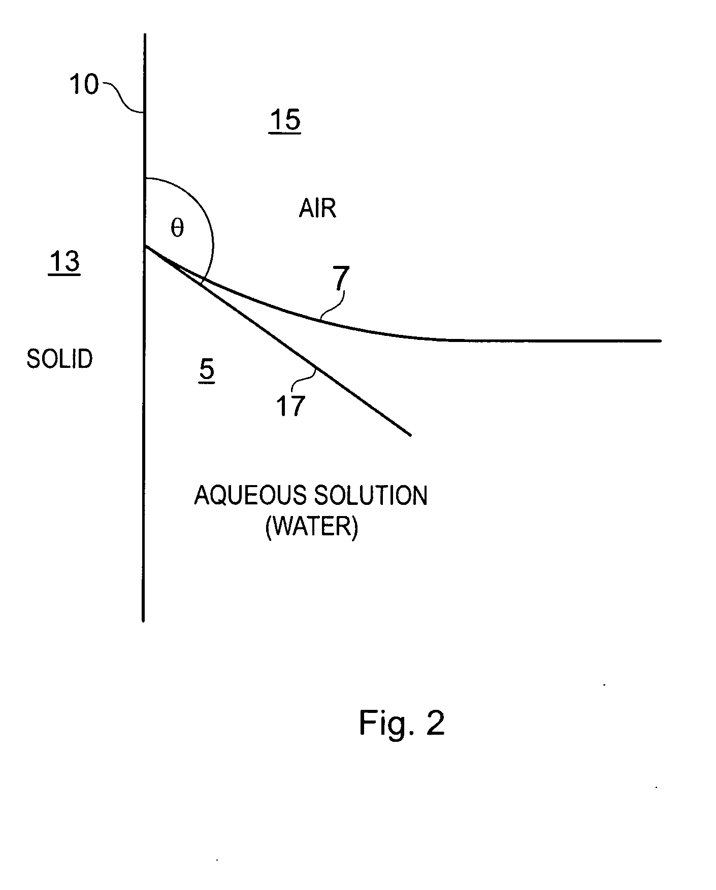
[0053]FIG. 2 illustrates an example meniscus 7 in a well plate. The shape of the meniscus can be explained by standard fluid mechanics. Namely, the situation that arises in a well plate is a specific example of contact at a surface (well plate side wall 10) between a solid (well plate material 13) and two immiscible fluids (air 15 and water 5). Here we describe the aqueous solution that is contained in the well plate as water for simplicity. Similarly, the ambient gaseous fluid is described as air, although other gases may be used, for example helium, nitrogen or another inert gas or gas mixture. Moreover, reference to aqueous solution does not exclude the possibility that constituents other than water are in the liquid in solution or otherwise. For example, a solvent may be present for killing cells or other reasons.

[0054]Surface tension forces a...


PUM


Abstract

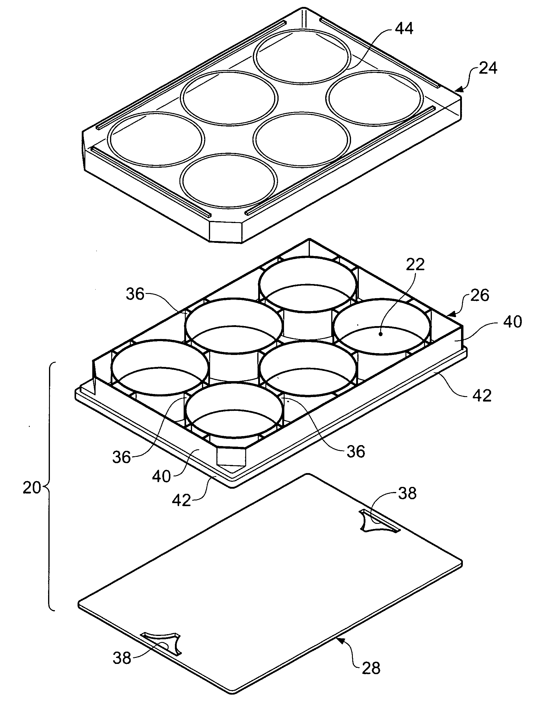
A well plate of non-unitary construction. The well plate is constructed from a first part of interconnected tubes that define the side walls of each well and a second part defining the well bases. The hydrophobicity of the first part is selected to suppress meniscus formation in the wells, thereby assisting optical characterization of samples in the wells, in particular by phase contrast microscopy. This can be achieved by using a natural cycloolefin copolymer (COP) which is not subjected to the usual plasma treatment to improve its wetting. The second part is formed of a single transparent sheet of hydrophilic material, such as a COP, which is bonded to the first part, for example ultrasonically.

Description

BACKGROUND OF THE INVENTION[0001]The present invention generally relates to well plates.[0002]Well plates are used widely for handling liquid samples in chemical and biological studies in fields such as gene sequencing, combinatorial chemistry, drug discovery and proteomics. Well plates can be used in automated and integrated systems and methods for rapidly identifying chemicals with biological activity in liquid samples, particularly automated screening of low volume samples for new medicines, agrochemicals, or cosmetics.[0003]The samples, e.g. cells or cell colonies, held in liquid in the well plates often need to be analyzed optically, which may be in microscope imaging, but commonly involves some form of spectroscopic measurements, such as fluorescence measurements of chemical or biological samples. For example, samples are often fluorescently tagged.[0004]A number of multi-well well plate platforms are commercially available from different vendors for culturing cells or perform...

Claims


Application Information

Patent Timeline
IPC IPC(8): B01L3/00
CPCB01L3/5085B01L2300/0829B01L2300/161G01N21/6452C12M23/22G01N21/0303C12M23/12
Inventor JIANG, YONGGANG
Owner GENETIX LTD
Learn More