Exhaust purification catalyst warm-up system of an internal combustion engine and method of the same

Inactive Publication Date: 2007-11-29
TOYOTA JIDOSHA KK
View PDF3 Cites 10 Cited by
  • Summary
  • Abstract
  • Description
  • Claims
  • Application Information

AI Technical Summary

Benefits of technology

[0013]Therefore, if the internal combustion engine is operated in an environment in which the atmospheric pressure is low, because of the reduction in the density of the air, the amount of secondary air supplied is substantially reduced, and there is a tendency for the amount of unburned components to reduce. With regard to this point, according to the above-noted constitution, because the degree of fuel increase is increased and the amount of unburned component that is combusted increases, the reduction in the amount of heat generated due to a reduction in the atmospheric pressure is suppressed, and it is possible to quickly activate the exhaust purifying catalyst.
[0014]In contrast to the above, if the internal combustion engine is operated in an environment having a high atmospheric pressure, because of the increased density of the air, the amount of secondary air supplied substantially increases, and the amount of unburned components that are combusted also increases. With regard to this point, according to the above-noted constitution, because the degree of fuel increase is reduced, the higher the atmospheric pressure is, so as to reduce the amount of unburned component that is combusted, a sudden increase in the amount of heat generated due to an increase in the atmospheric pressure is suppressed, and it is possible to suppress a deterioration of the exhaust purifying catalyst due to overheating.

Problems solved by technology

Even with the secondary air supplying device supplying air to the exhaust pipe of the internal combustion engine, because of insufficient mixing with unburned components of the fuel and a decrease in the exhaust temperature and the like, in actuality only a part of the supplied air and unburned components of the fuel is combusted.

Method used


Image

  • Exhaust purification catalyst warm-up system of an internal combustion engine and method of the same
  • Exhaust purification catalyst warm-up system of an internal combustion engine and method of the same
  • Exhaust purification catalyst warm-up system of an internal combustion engine and method of the same

Examples


Embodiment Construction

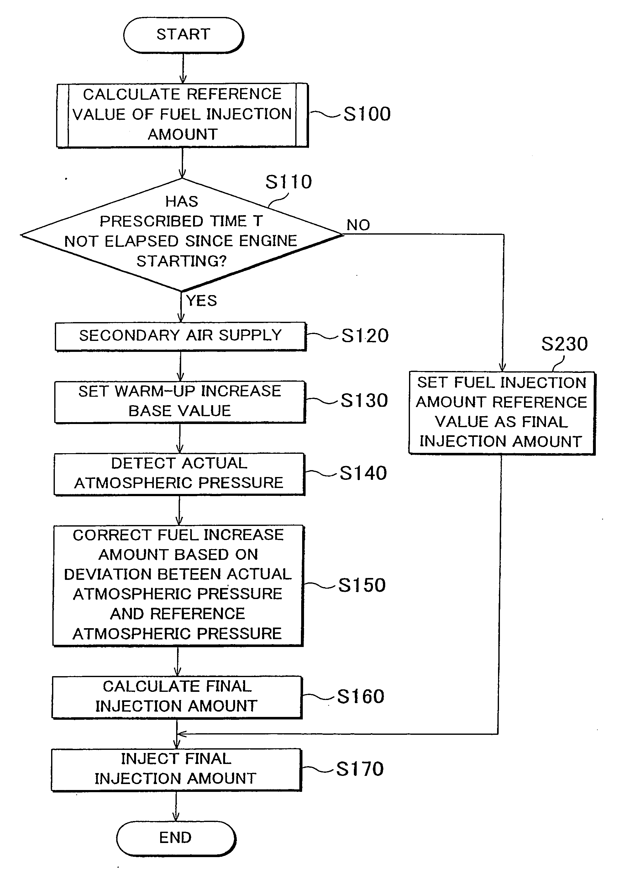
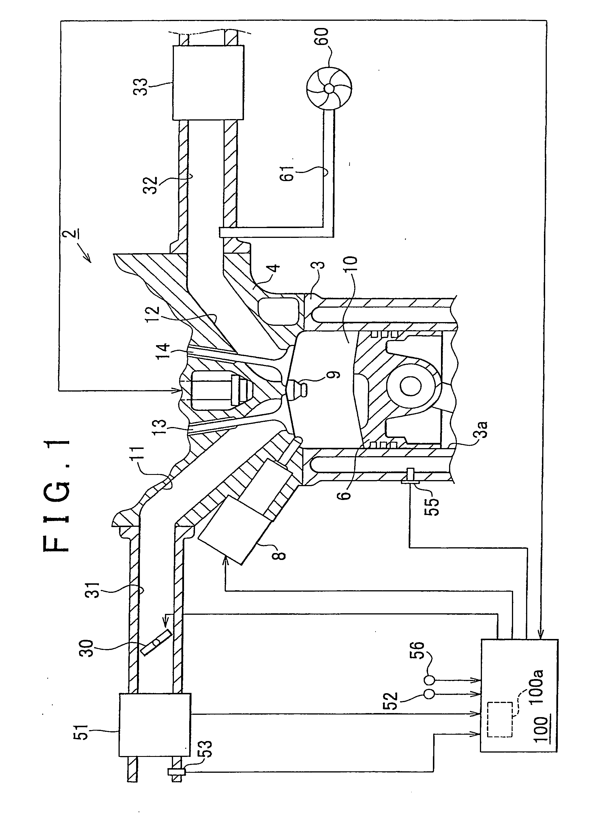
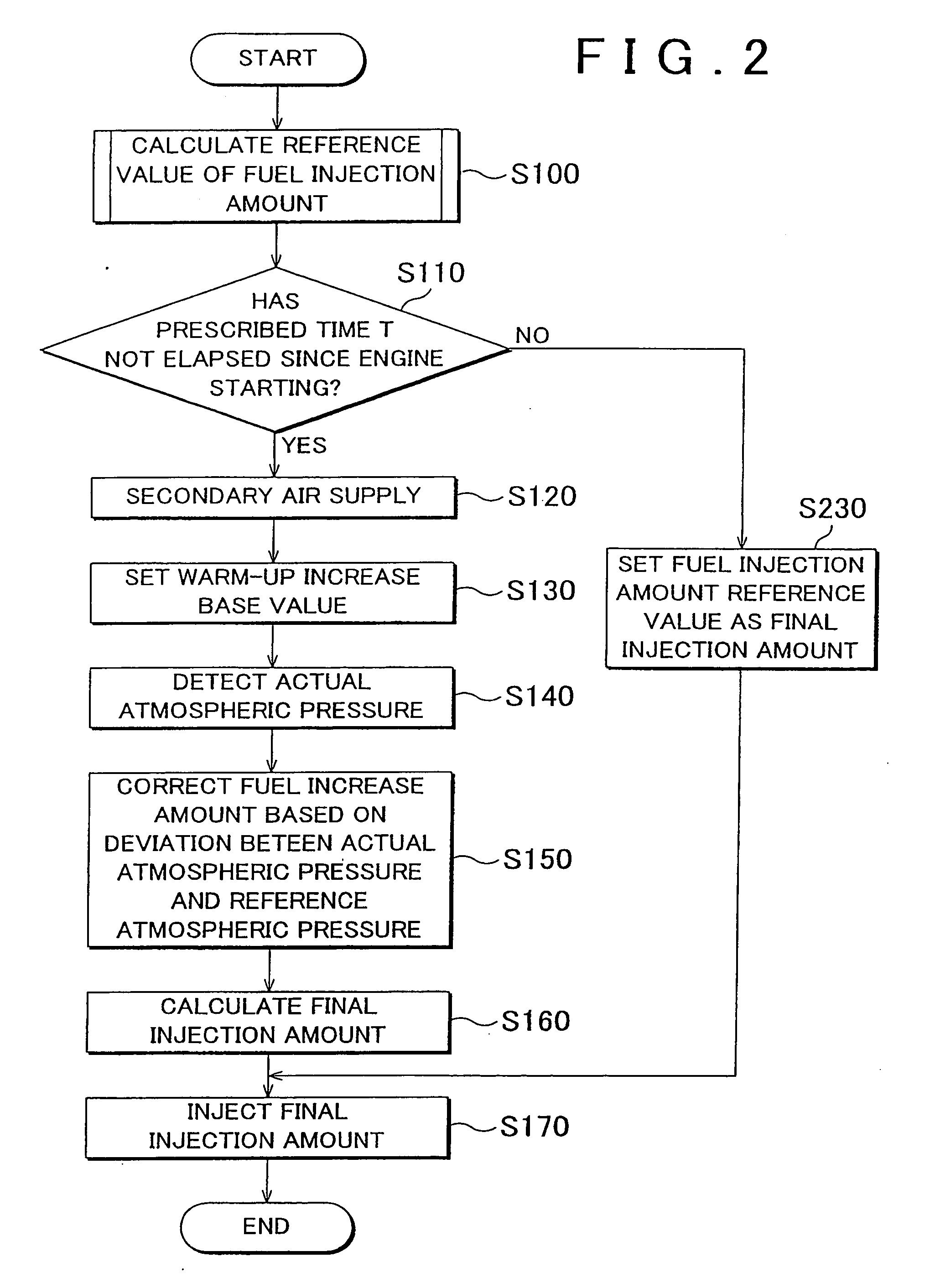
[0023]Example embodiments of the present invention are described in detail below, with references made to the accompanying drawings FIG. 1 to FIG. 3, of which FIG. 1 shows the configuration of an exhaust purification catalyst warm-up system for an internal combustion engine 2 mounted aboard a vehicle.

[0024]The structure of the internal combustion engine 2 will first be described. As shown in FIG. 1, a plurality of cylinders 3a (only one being shown in FIG. 1) are formed in the cylinder block 3 of the internal combustion engine 2. A piston 6 is provided within the cylinder 3a (only one being shown in FIG. 1) capable of reciprocating motion along the direction of the cylinder 3a. A cylinder head 4 is provided at the top of the cylinder block 3 as shown in the drawing, a combustion chamber 10 being delineated by the cylinder block 3, the cylinder head 4, and the piston 6.

[0025]An intake port 11 and an exhaust port 12 connected to the combustion chamber 10 are provided in the cylinder h...


PUM


Abstract

An exhaust purification catalyst warm-up system has an air pump that supplies air upstream from an exhaust purifying catalyst, disposed in an exhaust pipe of an internal combustion engine, the pump supplying air when the exhaust purifying catalyst is being warmed up. The exhaust purification catalyst warm-up system also has an atmospheric pressure sensor that detects the atmospheric pressure, wherein correction is performed so that the degree of fuel increase is smaller, the higher is the atmospheric pressure detected by the atmospheric pressure sensor.

Description

INCORPORATION BY REFERENCE[0001]The disclosure of Japanese Patent Application No. 2006-148343 filed on May 29, 2006 including the specification, drawings, and abstract is incorporated herein by reference in its entirety.BACKGROUND OF THE INVENTION[0002]1. Field of the Invention[0003]The present invention relates to an exhaust purification catalyst warm-up system and method for warming up an exhaust purification catalyst disposed in an exhaust pipe of an internal combustion engine.[0004]2. Description of the Related Art[0005]An exhaust purification catalyst that removes harmful components, such as carbon monoxide (CO) or nitrogen oxides (NOx) from exhaust gas, via oxidation-reduction action, is provided in the exhaust system of an internal combustion engine. Because an exhaust purification catalyst is not sufficiently activated until it reaches at least a prescribed temperature (for example, 350° C.), it might not be possible to efficiently remove such harmful components from the exh...

Claims


Application Information

Patent Timeline
IPC IPC(8): F01N3/00
CPCF01N3/0814F01N3/0842F01N3/2006F01N3/32F01N3/323F01N2430/06Y02T10/26F01N2570/12F01N2570/14F02D41/0255F02D41/40F02D2200/703F01N2570/10Y02T10/12
Inventor MURAGUCHI, TOMOKAZU
Owner TOYOTA JIDOSHA KK
Why Eureka
Try Eureka