
Hybrid Component

Active Publication Date: 2007-11-29
MAGNA INTERNATIONAL INC
View PDF13 Cites 50 Cited by
  • Summary
  • Abstract
  • Description
  • Claims
  • Application Information

AI Technical Summary

Benefits of technology

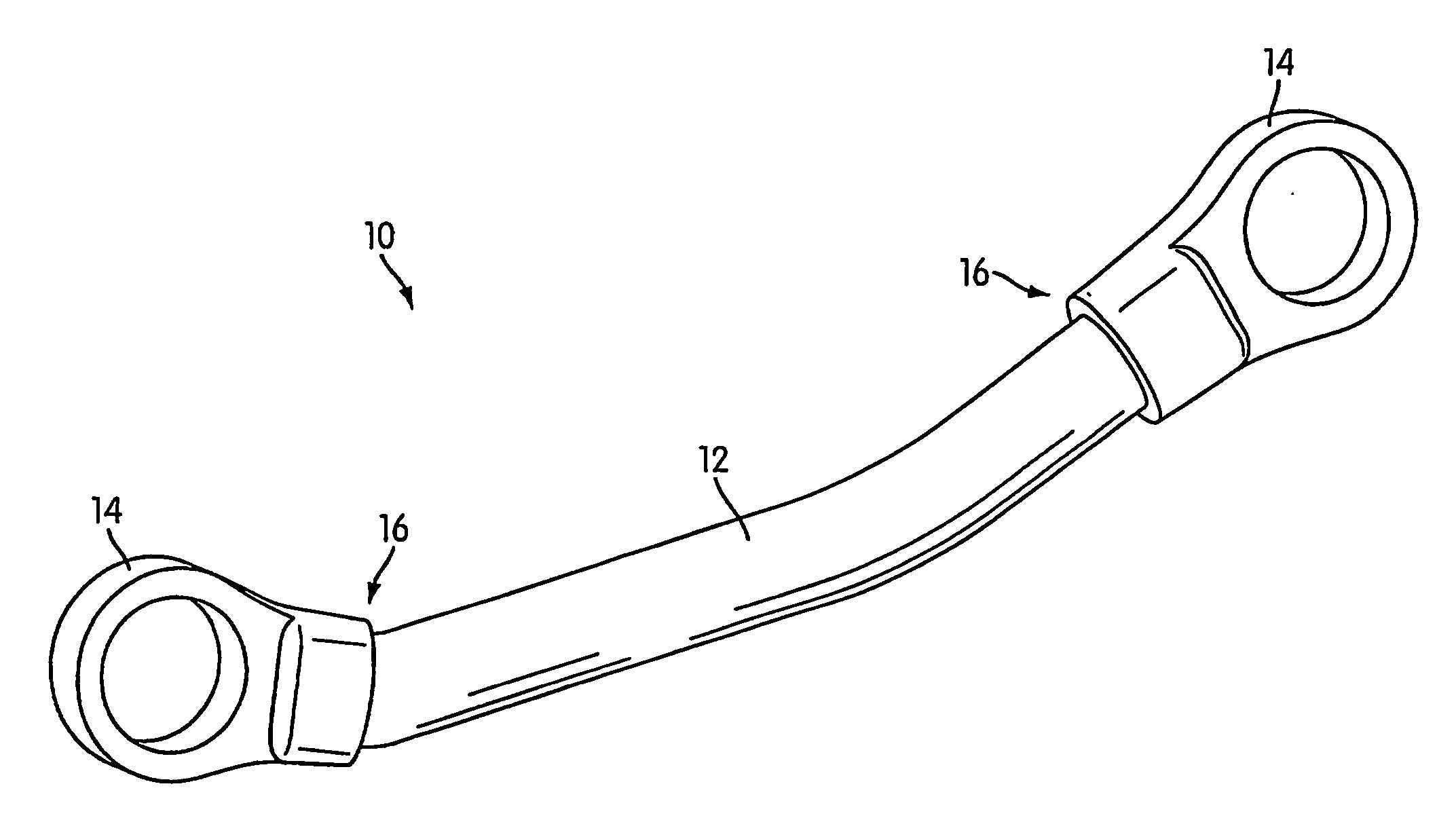
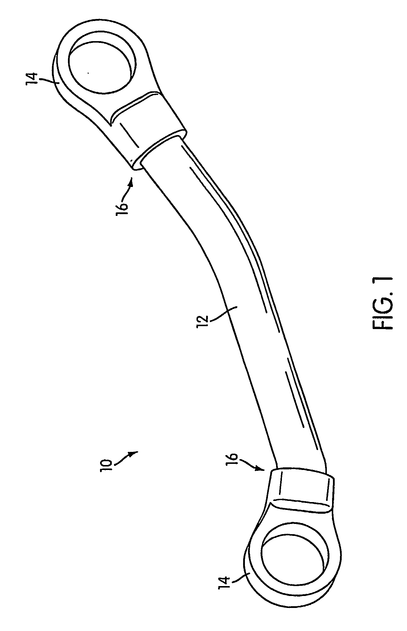
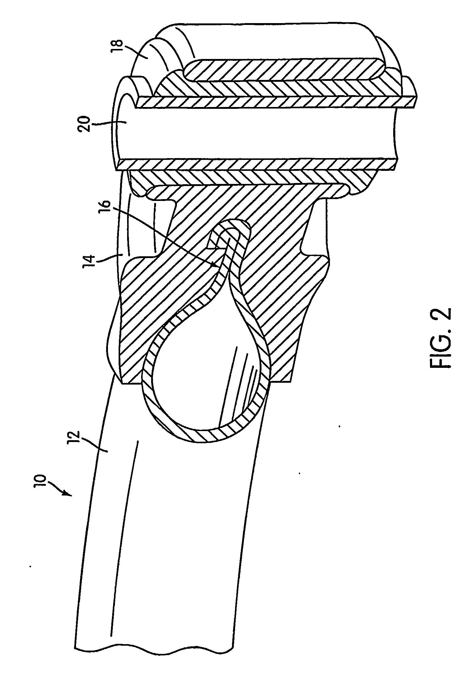
[0011] Another aspect of the invention relates to a hybrid component that includes a tubular member having a deformed open end, and a coupling member formed on the deformed open end of the tubular member by casting-in-place molten material about the deformed open end, thereby positively securing the coupling member to the tubular member.
[0015] Another aspect of the invention relates to a hybrid component for lightweight, structural uses. The hybrid component includes a steel member formed of a high strength steel, and a cast coupling member cast on a portion of the steel member by casting-in-place a semi-solid aluminum about the portion of the steel member, thereby positively and rigidly securing the coupling member to the steel member.
[0025] Another aspect of the invention relates to a method of forming a hybrid component for lightweight, structural uses. The method includes forming a steel member formed of a high strength steel into a predetermined configuration and casting a coupling member on a portion of the steel member by casting-in-place a semi-solid aluminum about the portion of the steel member, thereby positively and rigidly securing the coupling member to the steel member.

Problems solved by technology

However, a conventional suspension arm member, for example, in which the main body and the coupling member are joined by using a welding method, such as fusion welding (MIG welding, TIG welding, laser welding, or the like) or a solid-phase welding method (friction agitation welding), may cause cracks at or approximate to the joined portion when a tensile load is imparted thereto resulting in separation of the joined members and reduced functionality.

Method used


Image

  • Hybrid Component
  • Hybrid Component
  • Hybrid Component

Examples


Embodiment Construction

[0082] The subject application discloses a casting method employing a semi-solid casting process to fabricate structural components, e.g., automotive structural components, comprised of a preformed high strength steel insert and cast aluminum. The method involves placing a preformed and heat treated steel member, e.g., a tube, into a conventional steel die cast die, casting semi-solid aluminum around specific sections of the steel member, and creating a component comprised of dissimilar materials (e.g., steel and aluminum). The hybrid material (aluminum / steel) structural component may be subsequently heat treated (artificially aged at an elevated temperature of approximately 400 degrees F.) to a T5 heat treatment specification to improve the mechanical properties of the cast aluminum. Subsequent to the heat treatment process, the component may be machined and assembled using conventional processing and methods. (It should be understood that the reference to “steel” and “aluminum” ar...


PUM

PropertyMeasurementUnit
Angleaaaaaaaaaa
Yield strengthaaaaaaaaaa

Abstract

A hybrid component for lightweight, structural uses, including a steel member formed of a high strength steel; and a cast coupling member cast on a portion of the steel member by casting-in-place a semi-solid aluminum about the portion of the steel member, thereby positively and rigidly securing the coupling member to the steel member. A method of forming a hybrid component for lightweight, structural uses, including: forming a steel member formed of a high strength steel into a predetermined configuration; and casting a coupling member on a portion of the steel member by casting-in-place a semi-solid aluminum about the portion of the steel member, thereby positively and rigidly securing the coupling member to the steel member.

Description

[0001] The present invention is related to and claims priority from U.S. Provisional Patent Application 60 / 512,827 filed on Oct. 20, 2003, the entire contents being incorporated herein in its entirety. The present invention is also related to and claims priority from U.S. Provisional Patent Application 60 / 612,800 filed on Sep. 27, 2004, the entire contents being incorporated herein in its entirety.BACKGROUND OF THE INVENTION [0002] 1. Field of the Invention [0003] The present invention relates in general to an automotive component, and more specifically, to a hybrid component for use in an automobile suspension, chassis, body or power train component such as but not limited to control arm, engine mount, sub-frame or transmission pump that is at least partially formed by using a cast-in-place operation. [0004] 2. Description of the Related Art [0005] Typically, a conventional arm member for use as an automobile suspension arm is comprised of a machined aluminum casting, iron casting ...

Claims


Application Information

Patent Timeline
IPC IPC(8): B21D47/00B21D53/00B21D7/00B60R19/04B22D17/00B22D19/00B22D19/04B22D19/16B22D23/00
CPCB22D17/007B22D19/00Y10T29/49622B22D19/16B22D23/00B22D19/04B22D21/04C22C38/06
Inventor MELLIS, JEFFREY JAYGABBIANELLI, FRANKLANGLOIS, ERRYN LEIGHSULISZ, DANIELWERNER, MARK F.SKSZEK, TIMOTHY W.HORTON, FRANK A.YOUNG, WARRENKOTAGIRI, SEETARAMA S.KISELIS, P. GREGORYEGLE, DEWAYNE DALE
Owner MAGNA INTERNATIONAL INC
Learn More