
Kit for use in orthopaedic procedures, device and related menthod

a technology for orthopaedic procedures and menthods, applied in the field of orthopaedics, can solve the problems of stress on joints or damage to joints in the body, wear and tear of cartilage, and damage to other connective tissues such as tendons or ligaments, and achieves a wide range of final tension control, reduced friction, and greater maximum tension

Inactive Publication Date: 2007-11-22
DEPUY PROD INC
View PDF3 Cites 8 Cited by
  • Summary
  • Abstract
  • Description
  • Claims
  • Application Information

AI Technical Summary

Benefits of technology

[0030] The cable-tensioning device utilizes two binding mechanisms to hold the cable ends and a ratcheting pulley for creating an accurate tension control over a wide variety of tension forces.
[0039] The technical advantages of the present invention further include the ability to provide broader control of final tension and greater maximum tension for a tensioning of a cerclage cable. For example, according to another aspect of the present invention, a device for use in tensioning a cable around a long bone is provided. The device includes a body having first and second spaced apart arms and a connecting mean having a unidirectional locking mechanism for tightening the cable. The unilateral locking mechanism may include a low friction mechanism, such as a ratcheting mechanism that will provide for broad tension control and greater maximum tension. Thus, the present invention provides for a tensioning device with much broader control of final tension and greater maximum tension force.
[0040] The technical advantages of the present invention further include the ability to provide a orthopaedic cable-tensioning device with a simple mechanism. For example, according to another aspect of the present invention, a device for use in tensioning a cable around a long bone is provided. The device includes a body having a base and spaced apart arms extending from the base. The device further includes a first connecting means to connect a first end of the cable and a second connecting means for connecting the second end of the cable. The second connecting means includes a unidirectional locking mechanism for tightening the cable. The tightening mechanism may be a simple ratcheting mechanism and may, for example, be a pair of spring-biased wheels including teeth for providing the unidirectional locking mechanism. Thus the present invention provides for a cable-tensioning device with a simple mechanism.
[0041] The technical advantages of the present invention further include the ability to provide a tensioning device that is easy to manufacture and maintain. For example, according to another aspect of the present invention, a device for use in tensioning a cable around a long bone is provided. The device includes a body having spaced apart arms extending from the body. A connecting means is attached to one of the arms while a second connecting means is attached to the other arm. The second connecting mean may include a unilateral locking mechanism to tighten the cable. The unilateral locking mechanism may include a ratcheting mechanism in the form of a spring-biased pair of wheels including teeth for providing the ratcheting mechanism. This mechanism is easy to manufacture and simple to maintain. Thus, the present invention provides for a orthopaedic cable-tensioning device that is easy to manufacture and maintain.
[0042] The technical advantages of the present invention further include the ability to quickly and easily tension a cable around a long bone. For example, according to yet another aspect of the present invention, a device for use in tensioning a cable around a long bone is provided. The device includes a body with a pair of spaced apart arms extending from the base of the body. A first connecting means is used to secure one end of the cable while a second connecting means is used to secure and tighten the cable to the device. The second connecting means includes a unilateral locking mechanism in the form of, for example, a pair of spaced apart wheels having teeth, which are biased to provide for a unilateral locking mechanism. The unilateral locking mechanism is quickly and easily secured by means of a simple ratchet mechanism that is quick and easy to use. Thus, the present invention provides for a cable-tensioning device that is quick and easy to use.
[0043] The technical advantages of the present invention further include the ability to provide a cable-tensioning device with reduced components. For example, according to yet another aspect of the present invention, a tensioning device for tensioning a cable around a long bone is provided, including a body having an integral first connecting means in the form of, for example, an opening in the body for receiving a first end of a cable and a second connecting means in the form of a ratcheting mechanism. The ratcheting mechanism may include simply three components, a first wheel, a fastener to secure the first wheel to the body, and a spring for biasing the first wheel to the body. The body and the first wheel may include teeth to provide for the unilateral ratcheting mechanism. Thus the present invention provides for a tensioning device with a minimal number or a reduced amount of components.

Problems solved by technology

The joints in the body are stressed or can be damaged in a variety of ways.
Over time, the normal use of a joint may wear down the cartilage and bring the moving bones in a direct contact with each other.
In contrast, in normal use, a trauma to a joint, such as the delivery of a large force, from an accident for, example, an automobile accident, may cause considerable damage to the bones, the cartilage or to other connective tissue such as tendons or ligaments.
The insertion of the stem component of the total hip prosthesis into the medullary canal may cause the cortical bone to fracture, shatter or splinter.
The cable tensioner 10 of FIGS. 3A and 3B is complicated and expensive to manufacture.
The tensioner also may not provide accurate tension control.

Method used


Image

  • Kit for use in orthopaedic procedures, device and related menthod
  • Kit for use in orthopaedic procedures, device and related menthod
  • Kit for use in orthopaedic procedures, device and related menthod

Examples


Embodiment Construction

[0107] Embodiments of the present invention and the advantages thereof are best understood by referring to the following descriptions and drawings, wherein like numerals are used for like and corresponding parts of the drawings.

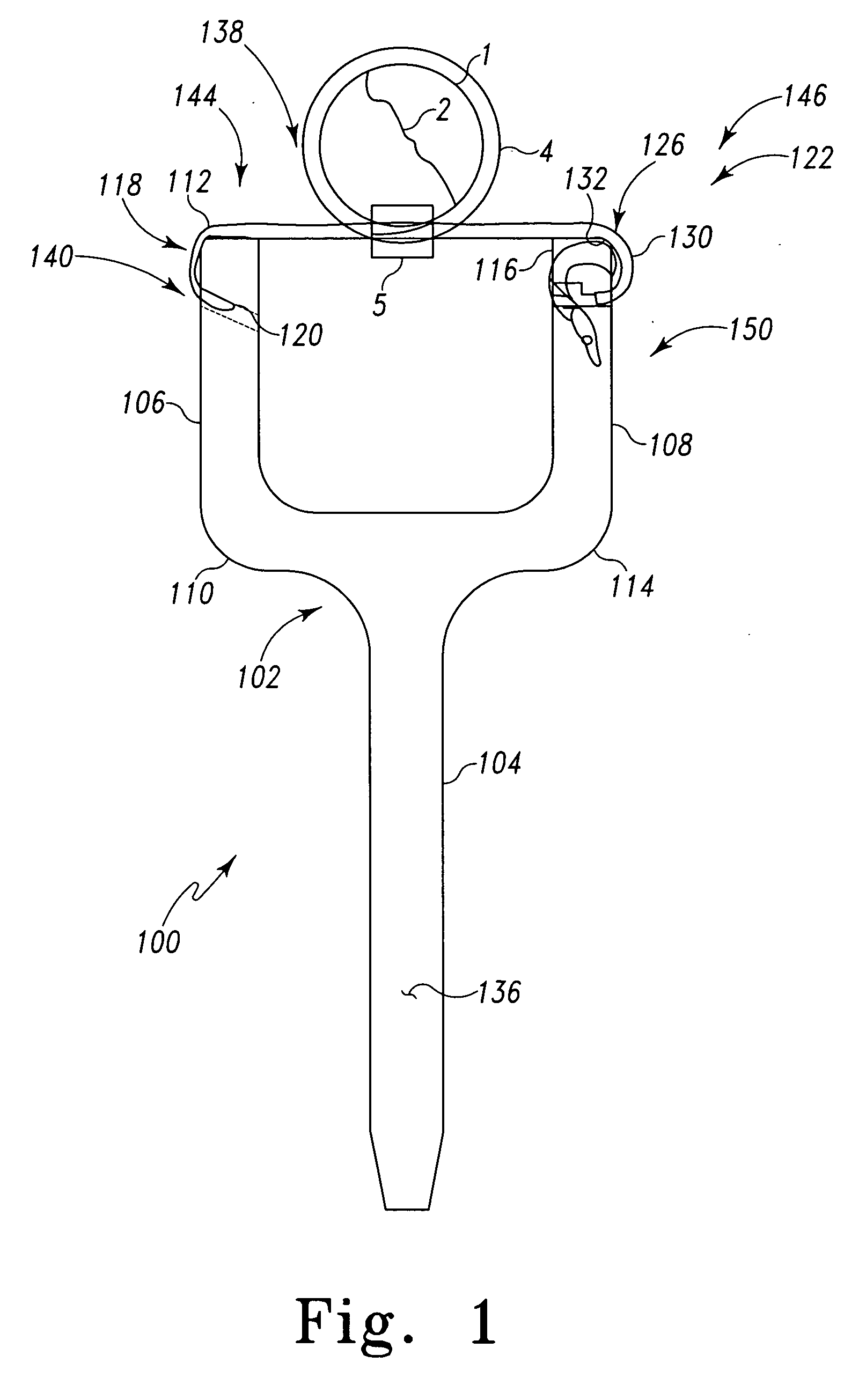
[0108] According to the present invention and referring now to FIG. 1, a device 100 for use in tensioning a cable 4 around long bone 1 for use in orthopaedic procedures is provided. The device 100 includes a body 102 having a base 104. A first arm 106 and a second arm 108 extend from the base 104 of the body 102 of the device 100. The first arm 106 includes a closed end 110 attached to the base 104 and an open end 112 opposed to the closed end 110. Similarly, the second arm 108 includes a closed end 114 attached to the base 104 and an open end 116 opposed to the closed end 114. The device 100 further includes first connecting means 118 operably associated with the body 102 for connecting a first end 120 of the cable 4 to the device 100.

[0109] The device 100...


PUM


Abstract

A kit for use in orthopaedic procedures on a long bone is provided. The kit includes a cable and a device. The device includes a body. The device also includes first connecting means operably associated with the body for connecting a first end of the cable to the device. The device also includes second connecting means operably associated with the body for connecting a second end of the cable to the device. The first connecting means and / or the second connecting means include a unidirectional locking mechanism for tightening the cable.

Description

TECHNICAL FIELD OF THE INVENTION [0001] The present invention relates generally to the field of orthopaedics, and more particularly, to an implant for use in arthroplasty. CROSS-REFERENCE TO RELATED APPLICATIONS [0002] Cross-reference is made to the following application: DEP5496USNP titled, “TENSIONING DEVICE, KIT AND RELATED METHOD” filed concurrently herewith which are incorporated herein by reference. BACKGROUND OF THE INVENTION [0003] Patients who suffer from the pain and immobility caused by osteoarthritis and rheumatoid arthritis have an option of joint replacement surgery. Joint replacement surgery is quite common and enables many individuals to function properly when it would not be otherwise possible to do so. Artificial joints are usually comprised of metal, ceramic and / or plastic components that are fixed to existing bone. [0004] Such joint replacement surgery is otherwise known as joint arthroplasty. Joint arthroplasty is a well-known surgical procedure by which a disea...

Claims


Application Information

Patent Timeline
Patent Type & Authority Applications(United States)
IPC IPC(8): A61B17/56
CPCA61B17/82A61B17/8861A61B17/8869A61F2/32A61F2/34A61F2/36A61F2250/0026A61F2/3676A61F2002/30322A61F2002/30827A61F2002/3611A61F2002/3625A61F2002/365A61F2/367
Inventor LEISINGER, STEVEN R.
Owner DEPUY PROD INC
Learn More