
Frequency offset correction for an ultrawideband communication system

a communication system and ultrawideband technology, applied in the field of frequency offset compensation, can solve the problems of receiving device not being able to correctly determine the value of received data, improper decoding of bits, and inability to properly decode bits, so as to improve the initial frequency offset estimate

Active Publication Date: 2007-11-22
REALTEK SEMICON CORP +1
View PDF4 Cites 75 Cited by
  • Summary
  • Abstract
  • Description
  • Claims
  • Application Information

AI Technical Summary

Benefits of technology

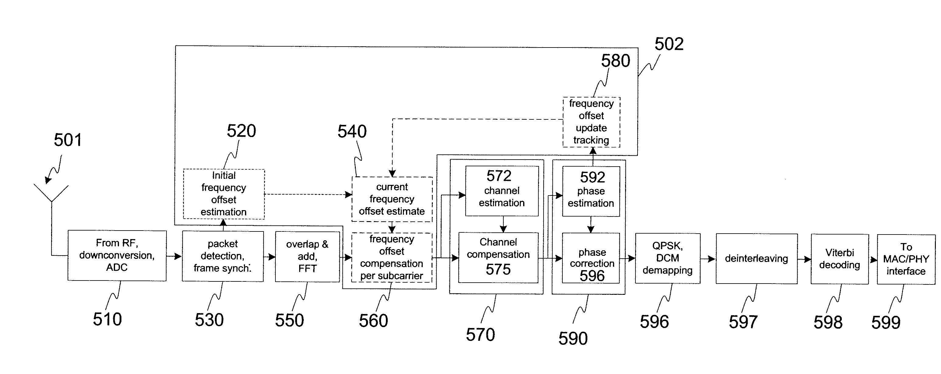
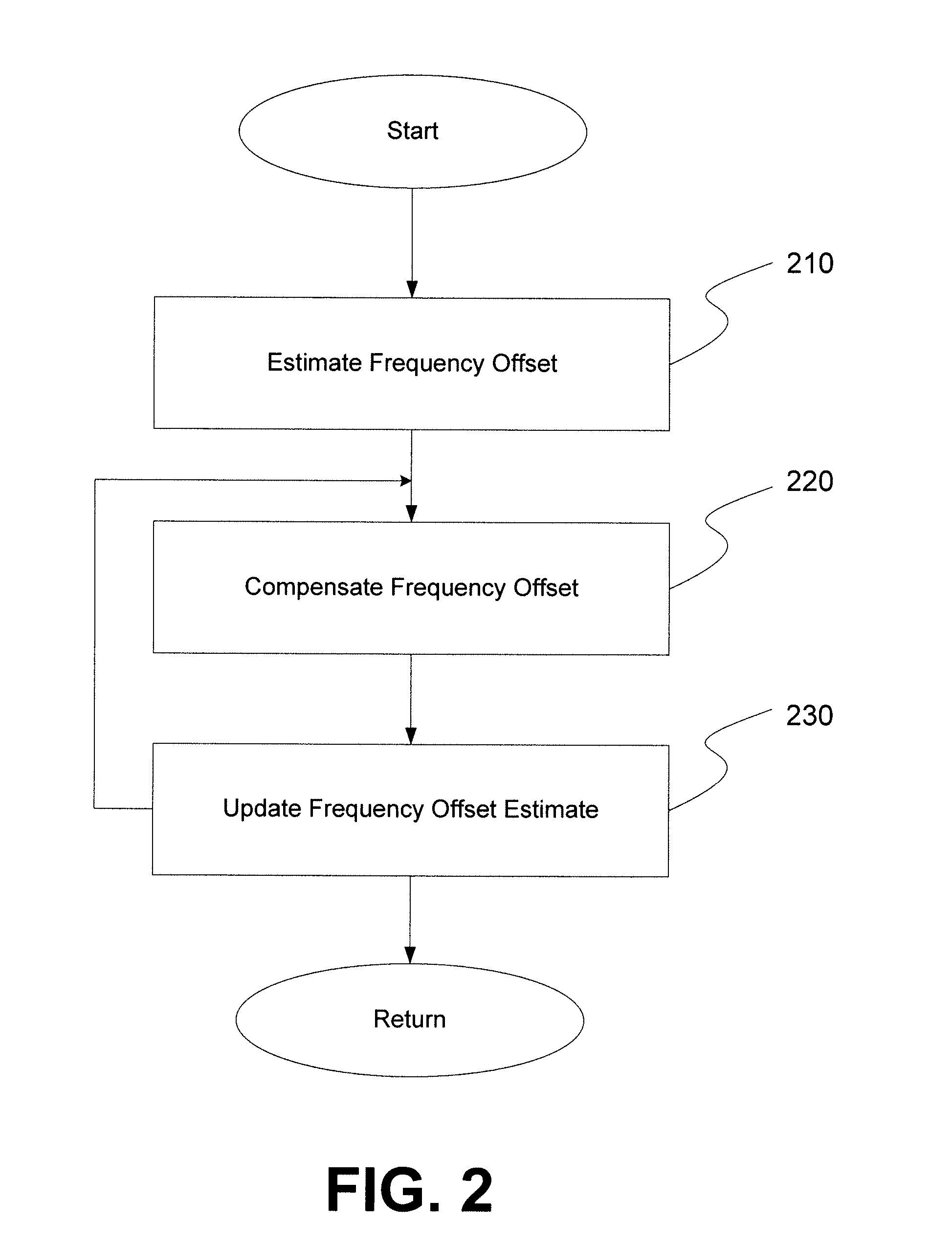
[0009] In one aspect, a receiver performs initial frequency offset estimation, frequency offset compensation, and frequency offset update tracking. The receiver of the embodiments of the invention estimates an initial frequency offset during preamble transmission, compensates the phase rotation per subcarrier based on the initial frequency estimate by performing complex multiplications after the FFT at the receiver, and improves the initial frequency offset estimate over the duration of the packet by measuring the residual phase rotation after frequency offset compensation, to fine-tune / refine the initial frequency offset estimate. After each update, the receiver compensates the phase rotation per subcarrier based on an updated and current frequency estimate.

Problems solved by technology

Unfortunately, oscillator output very often include variations between oscillators due to manufacturing and temperature variations, such that the frequency of an output oscillation signal may vary slightly from oscillator to oscillator.
This phase shift may result in the receiver being unable to correctly determine values for received data.
Phase shift in such a received signal may result in an improper decoding of the bits.
Similarly, phase shift of received signals which are encoded and decoded in the frequency domain may also result in phase rotation of signals transformed to the frequency domain, again resulting in an improper decoding of bits.
Moreover, the transmitters may operate in a bursty fashion, for example providing data in relatively short bursts followed by potentially lengthy periods of inactivity, imposing tight timing requirements on accounting for frequency offset.

Method used


Image

  • Frequency offset correction for an ultrawideband communication system
  • Frequency offset correction for an ultrawideband communication system
  • Frequency offset correction for an ultrawideband communication system

Examples


Embodiment Construction

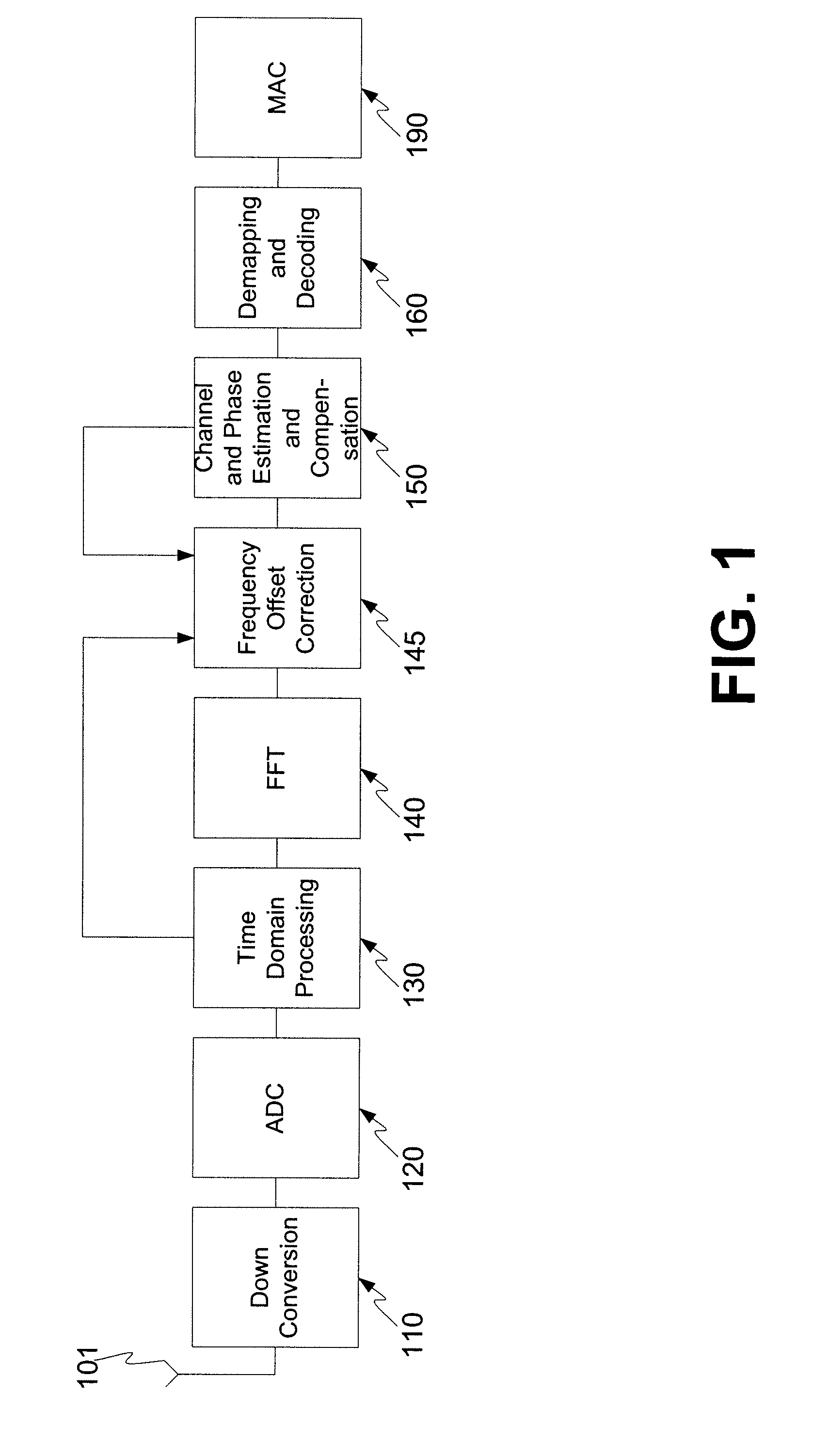
[0024]FIG. 1 is a block diagram of a receiver in accordance with aspects of the invention. The receiver of FIG. 1, for example, may be used in an ultrawideband communication system making use of OFDM symbols. The receiver includes an antenna 101 for receiving signals and a number of processing blocks for and processing received signals. As illustrated in FIG. 1, the processing blocks include an amplification and down conversion block 110, an analog to digital conversion block 120, a time domain processing block 130, a Fast Fourier Transform (FFT) block 140, a frequency offset correction block 145, a channel and phase estimation and compensation block 150, and a remapping and decoding block 160. Also shown in FIG. 1 is a media access controller (MAC) 190, which often is not considered part of the receiver, but is nevertheless shown in FIG. 1 to illustrate a downstream recipient of signals received and processed by the receiver. The various blocks of the receiver are shown as 110, 120...


PUM


Abstract

A method and a receiver system for subcarrier-specific frequency offset correction including frequency offset estimation, updating and compensation. The method includes initial frequency offset estimation in time domain using packet preamble, frequency offset compensation during channel estimation symbols using the initial frequency offset estimate, and frequency offset update tracking during header and data part both being performed in the frequency domain. The initial frequency offset estimation includes using a sum over a number of time lagged autocorrelation results, corresponding to a number of the last consecutive symbols of the preamble part of the packet with the autocorrelations being the result of a sum over a window of cross-correlations between the incoming signal and the respective packet synchronization sequence. The receiver includes receiver blocks for initial frequency offset estimation, frequency offset compensation, frequency offset update tracking and obtaining a current frequency offset estimate.

Description

CROSS-REFERENCE TO RELATED APPLICATION(S) [0001] This Application claims the benefit of U.S. Provisional Patent Application No. 60 / 788,610, filed on Apr. 3, 2006, incorporated by reference herein.BACKGROUND OF THE INVENTION [0002] The present invention relates generally to frequency offset compensation, and more particularly to frequency offset compensation in an ultrawideband receiver. [0003] Communication systems often pass information from a transmitter to a receiver in a manner that makes use of a periodic signal. The periodic signal in many cases is not commonly shared between the transmitter and the receiver, such as by being provided to the receiver by the transmitter. Instead the transmitter and the receiver each generate their own periodic signal at appropriate frequencies. [0004] Generally the periodic signals are based on a relatively low frequency signal from a single oscillator, such as crystal oscillator, an LC tank oscillator, a ring oscillator or some other oscillato...

Claims


Application Information

Patent Timeline
IPC IPC(8): H04L27/28
CPCH04B1/7183
Inventor BRINK, STEPHAN TENMAHADEVAPPA, RAVISHANKAR H.
Owner REALTEK SEMICON CORP
Learn More