
Metal gasket

a technology of metal gaskets and gaskets, which is applied in the direction of engine seals, machine/engines, and sealing arrangements, etc., can solve the problems of increasing the creep relaxation of the straight line portion of the half bead, water leakage or oil leakage, and reducing the sealing surface pressure. , to achieve the effect of excellent sealing quality

Inactive Publication Date: 2007-11-22
ISHIKAWA GASKET CO LTD
View PDF36 Cites 11 Cited by
  • Summary
  • Abstract
  • Description
  • Claims
  • Application Information

AI Technical Summary

Benefits of technology

[0012]According to the structure, the surface pressure assistance plate forming the depressions and the projections is arranged with respect to the thickness direction, so that compressibility of the half bead can be enhanced due to an elastic effect by the depressions and the projections of the surface pressure assistance plate, and creep relaxation of the half bead can be prevented.
[0013]Also, members disposed on both sides of the metal gasket and abutting against the half bead hit a corner part of the half bead from an area close to a narrow line to an area of a wide surface. In addition, the maximum value of the surface pressure can be decreased and the surface pressure can be reduced, and the surface pressure generated on the half bead, especially, the surface pressure generated at the corner part of the half bead can be reduced. Accordingly, a scratch in a member clamping the metal gasket can be prevented and an excellent seal quality can be secured.
[0014]Also, in the metal gasket, the direction of top parts of the depressions and the projections of the surface pressure assistance plate is a direction intersecting with the half bead all around the half bead or a part of the perimeter of the half bead. With such a structure, the elastic effect due to the depressions and the projections of the surface pressure assistance plate can be used more efficiently than the structure in which the direction of the top parts of the depressions and the projections is arranged parallel to the half bead.
[0018]Moreover, instead of disposing the surface pressure assistance plate between the sloping part and the flat part of the half bead, the surface pressure assistance plate may be disposed on the outer perimeter side of the sloping part and inside the flat part on the outer perimeter side of the half bead. In this case, the surface pressure moderation effect on the corner part of the half bead is somewhat little. However, the elasticity of the half bead can be increased by the elasticity of the surface pressure assistance plate, so that it is expected that the creep relaxation be prevented.
[0020]According to the metal gasket of the present invention, the creep relaxation in the half bead around the seal target bore of the metal gasket can be prevented, and a scratch of a member clamping the metal gasket can be prevented by widening the distribution of the surface pressure generated in the half bead, so that an excellent seal quality can be secured.

Problems solved by technology

This straight line portion has proven to cause a problem such as water leakage or oil leakage during engine operation as compared to a curved line portion.
It is commonly believed that the reason the straight line portion easily creates the above-mentioned problem is that a creep relaxation in the straight line portion of the half bead increases during the operation of an engine wherein the gasket is equipped, so that the seal surface pressure partially decreases.
Accordingly, the creep relaxation is generated in this half bead, so that the seal quality cannot be fully exerted.
However, in order to form this kind of half beads, a space is required around the liquid hole (seal target hole), so that they are not practical.
Accordingly, a force compressing the half bead also increases, so that the serious problem is a creep relaxation of the half bead.
In addition, in the metal gaskets, the tightening pressure differs depending on the distance from the tightening bolt bore, so that the seal surface pressure generated in the half beads is also uneven.

Method used


Image

  • Metal gasket
  • Metal gasket
  • Metal gasket

Examples


Embodiment Construction

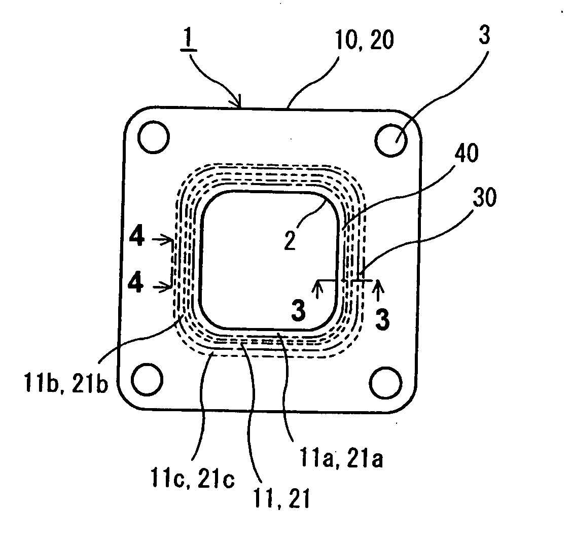
[0045]Hereunder, a metal gasket according to embodiments of the present invention will be explained with reference to the attached drawings.

[0046]Incidentally, FIGS. 1-24 are schematic explanatory views in which sizes of a seal target bore, bolt holes and half beads; widths of a middle plate and a surface pressure assistance plate; and thicknesses of a metal plate, middle plate and the surface pressure assistance plate; and sizes of depressions and projections are different from actual ones and enlarged for the sake of explanation. Also, for the sake of simplicity, hereunder, the seal target bore will be explained as one seal target bore. However, the present invention can be applied even when multiple kinds of seal target bores such as gas circulation holes, combustion chamber holes (bore holes), water holes, or oil holes, are respectively provided with multiple numbers, such as a gasket for an exhaust manifold for a multiple cylinder engine or a cylinder head gasket. Incidentally,...


PUM

PropertyMeasurementUnit
thicknessaaaaaaaaaa
perimeteraaaaaaaaaa
shapeaaaaaaaaaa

Abstract

A metal gasket includes first and second metal plates laminated together to form the metal gasket, and having holes to be sealed. At least one of the first and second metal plates has a half bead surrounding the hole. A surface pressure assistance plate is located at least adjacent to the half bead between the first and second metal plates. The assistance plate has depressions and projections with respect to a thickness direction thereof in at least a peripheral part thereof.

Description

BACKGROUND OF THE INVENTION AND RELATED ART STATEMENT [0001]The present invention relates to a metal gasket such as a gasket for an exhaust manifold for an engine, or a cylinder head gasket.[0002]When a joint surface between an exhaust manifold and an exhaust pipe for an automobile engine, or a joint surface between a cylinder head and a cylinder block (cylinder body) is sealed, a metal gasket is clamped between these members to seal combustion gas, coolant water, and lubrication oil.[0003]Such a metal gasket is made by a design method, in which, mainly as sealing means, a full bead with a projected cross-section and a half bead with a step-like (crank-like) cross-section are arranged near the perimeter of a seal target hole. Among them, the half bead can be produced at a low cost, and easily sealed by a small fastening force, so that it is widely used for gasoline engines with a small fastening force compared to diesel engines.[0004]With respect to the metal gasket with this half b...

Claims


Application Information

Patent Timeline
Patent Type & Authority Applications(United States)
IPC IPC(8): F02F11/00F01N13/10
CPCF16J15/0825F16J2015/0862F16J2015/085F16J15/00F16J15/08
Inventor IMAI, TOSHIHIRO
Owner ISHIKAWA GASKET CO LTD
Learn More