Electro-mechanical clutch

a technology of electromechanical and clutch, applied in the direction of power-operated mechanism, door/window fitting, coupling, etc., can solve the problems of inconvenient and costly operation, drag caused by permanent magnet, and difficulty in opening and closing the tailgate, etc., and achieve the effect of higher torqu

Inactive Publication Date: 2007-11-22
ARVINMERITOR LIGHT VEHICLE SYST FRANCE
View PDF4 Cites 12 Cited by
  • Summary
  • Abstract
  • Description
  • Claims
  • Application Information

AI Technical Summary

Benefits of technology

[0006]Thus, the present invention provides a clutch that includes an input pinion, and an output pinion associated with a rotatable locking member with a surface inclined with respect to an axis of rotation. The surface cooperates with an engagement member, and the rotatable locking member is movable between a first position and a second position. In the first position, the surface forms a recess to receive the engagement member. In the second position, the surface forms a projection to force the engagement member into abutment with the input pinion to establish a driveable connection between the input pinion and the output pinion. The surface amplifies a force that acts on the engagement member, which results in a higher torque that can be transmitted in a small clutch package.
[0014]The clutch is advantageously used in a mechanism moving an aperture such as a tailgate, a trunk lid, a hatchback or a sliding door, for example. When the mechanism is in a normal automatic mode, the mechanism is driven by a motor, and motor torque is transmitted through the clutch. When the motor is stopped, for example in the event of a power failure or if the user wants the aperture to be held in an intermediate position, the electromagnetic coil can be deactivated. The permanent magnet will produce enough force in the clutch to hold the aperture in the position the aperture was in when the current was stopped. In this position, the aperture can be moved electrically or manually. If the aperture is moved manually, a sensor can be provided in the system, which informs a control system of a manual movement. As soon as the movement stops during a defined time, the control system can activate the electromagnetic coil again so that the locking member is returned to the second position and the clutch is closed. Therefore, in the case of battery failure, even in the middle of an automatic maneuver when the clutch is engaged, the manual maneuver will automatically declutch the system and permit a movement with no drag on the clutch.

Problems solved by technology

Therefore, in order to have an electromagnetic clutch that transfers a large torque, packaging and weight of the electromagnetic clutch must be increased, which is inconvenient and costly.
However, the drag caused by the permanent magnet is very uncomfortable for a user operating a tailgate manually in the event of a power failure because the presence of drag means that it is very difficult to open and close the tailgate.

Method used


Image

  • Electro-mechanical clutch
  • Electro-mechanical clutch

Examples


Embodiment Construction

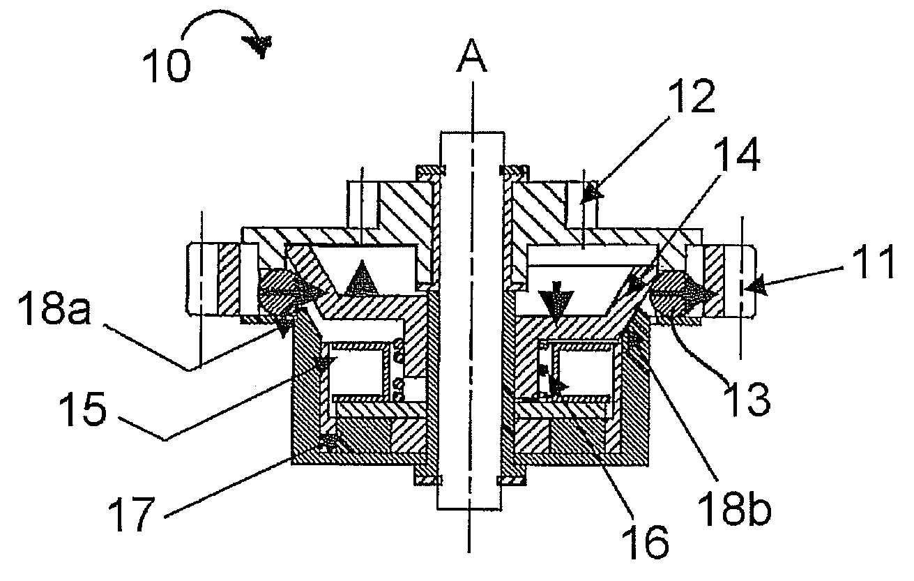
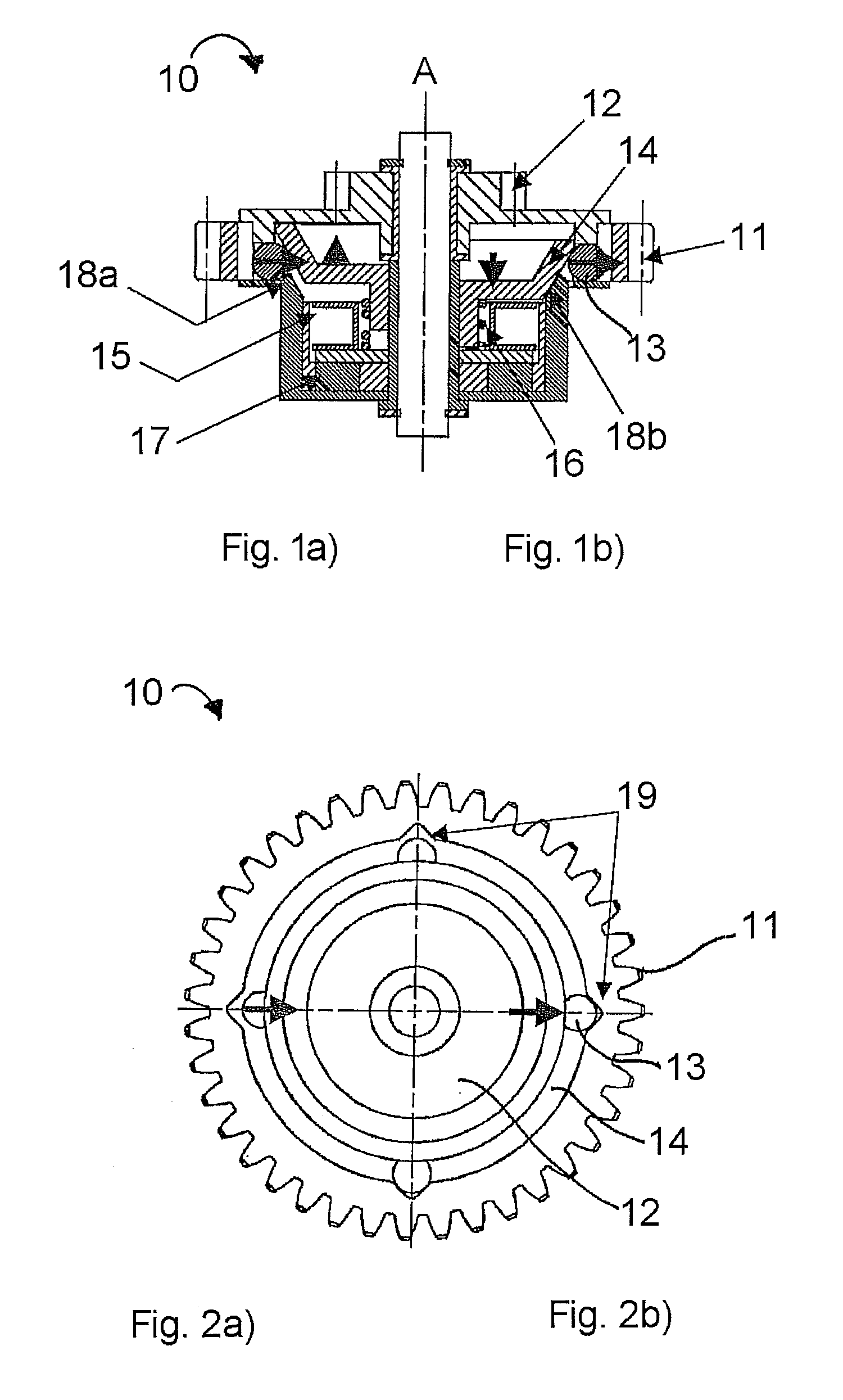
[0020]Referring now to FIGS. 1a)-1b) and 2a)-2b), a clutch 10 has an input pinion 11 connected to a drive mechanism (not shown), for example an electric motor, which causes the input pinion 11 to rotate. The clutch 10 also has an output pinion 12 that is connected to a moving mechanism (not shown) that moves a tailgate, for example. The output pinion 12 is rotatable about a central axis of rotation A and is arranged to be freely rotatable on a central shaft. The input pinion 11 is provided with notches 19.

[0021]Associated with the output pinion 12 is a frustro-conical locking member 14 that has an inclined surface. The locking member 14 is also rotatable about the central axis of rotation A and is arranged rotatably on the central shaft to be capable of rotating synchronously with the output pinion 12. The inclined surface of the locking member 14 tapers inwards towards the end of the locking member 14 furthest away from the output pinion 12. A plurality of engagement members 13 is ...


PUM


Abstract

A clutch comprises an input pinion and an output pinion associated with a rotatable locking member that has a surface inclined with respect to an axis of rotation of the locking member. The surface cooperates with an engagement member, and the locking member is movable between a first position and a second position. In the first position, the surface forms a recess to receive the engagement member, and in the second position, the surface forms a projection to force the engagement member into abutment with the input pinion to establish a driveable connection between the input pinion and the output pinion.

Description

RELATED APPLICATIONS[0001]The application claims priority to German Application No. 10 2006 023 447.2, which was filed on May 18, 2006.BACKGROUND OF THE INVENTION[0002]The present invention generally relates to an electromechanical clutch. More particularly, but not exclusively, the present invention relates to an electromechanical ball clutch for use in a power driven system such as a motorized tailgate or hatchback door for a vehicle, for example.[0003]In power driven systems, there is a need to provide a manual back-up mode in case there is a battery failure, for example. Such a manual back-up mode should provide an effort similar to a standard manual system. It is necessary to disengage a drive unit during the manual back-up mode and also when a user wishes to operate the system manually. One way of allowing disengagement of the drive unit is to provide an electromagnetic clutch between mechanical elements, for example between a motor and a reduction unit that benefits from a lo...

Claims


Application Information

Patent Timeline
Patent Type & Authority Applications(United States)
IPC IPC(8): F16D27/102
CPCE05Y2400/302E05Y2800/11E05Y2900/548E05F15/611E05Y2201/236E05F15/603F16D27/108
Inventor BENOIT, DOMINIQUERIVOIRET, FRANCKPEBRE, THIERRY
Owner ARVINMERITOR LIGHT VEHICLE SYST FRANCE
Why Eureka
Try Eureka