
Building Structure and a Method of Forming a Building Structure

a technology of building structure and building structure, applied in the direction of underwater structures, building components, artificial islands, etc., can solve the problem of restricting the economic use of a si

Inactive Publication Date: 2007-11-22
LYDEN PAUL JOHN
View PDF0 Cites 24 Cited by
  • Summary
  • Abstract
  • Description
  • Claims
  • Application Information

AI Technical Summary

Benefits of technology

[0027] Advantageously we have found that by the use of the building structure of the present invention, the need to over-excavate is substantially reduced or eliminated as there is no longer a requirement to access the external side of the wall as the panels may be placed in situ with the waterproofing membrane in place. As such, it is possible to allow for the maximum utilisation of the building site as there is no need to allow space for the over-excavation of the walls.
[0028] As a result of the use of the building structure of the present invention a dramatic reduction in the construction program for the basement work may be achieved. We have found that up to 50% of the work required to construct the basement of a building structure may be saved. In addition, the requirement for a variety of trades may be reduced or eliminated. We have found that it is possible to reduce or eliminate the need for concreters, form workers, steel fixers and waterproofers.
[0029] The building structure of the present invention may be produced in a manner which permits the saving of a variety of other services such as water, electricity, cranage and the like. In addition the need for onsite storage and accommodation may be reduced.

Problems solved by technology

Larger structures which are built on inground foundations are notoriously difficult to waterproof and current procedures that are used to provide waterproofing require peripheral excavation which are time consuming and costly and depending on site conditions, may restrict economic use of a site.

Method used


Image

  • Building Structure and a Method of Forming a Building Structure
  • Building Structure and a Method of Forming a Building Structure
  • Building Structure and a Method of Forming a Building Structure

Examples


Embodiment Construction

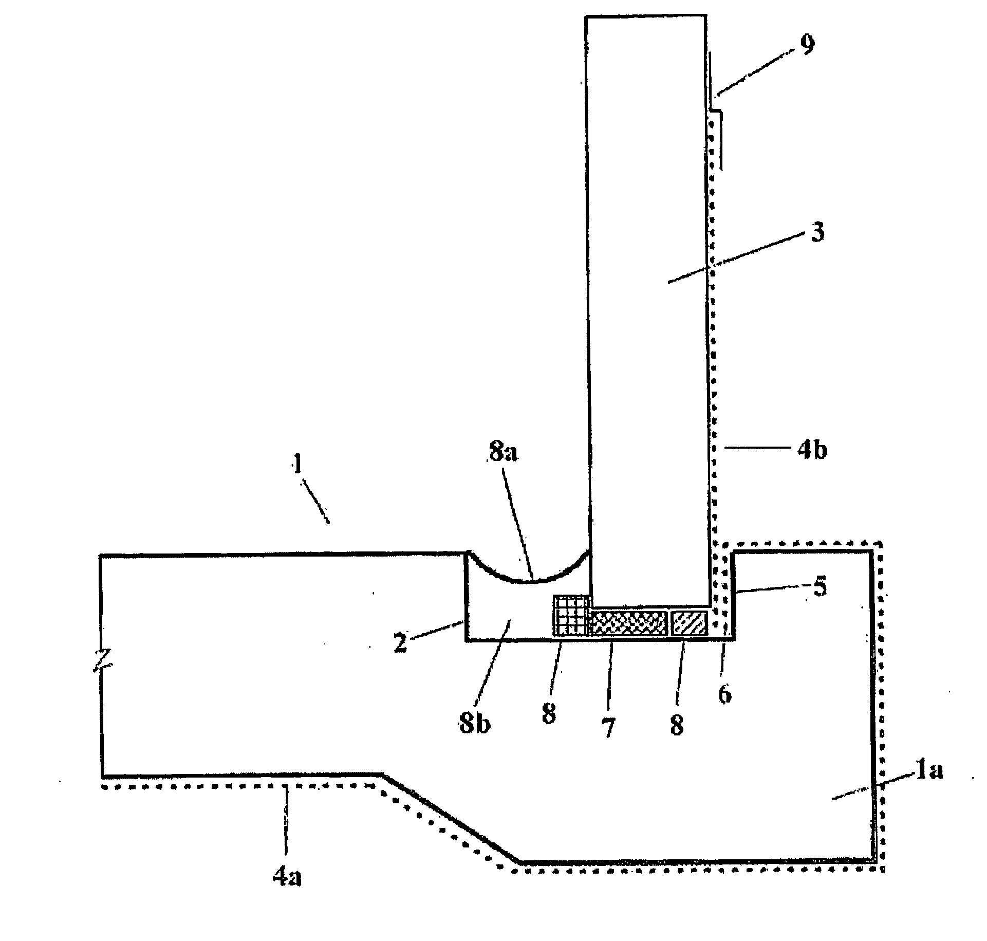
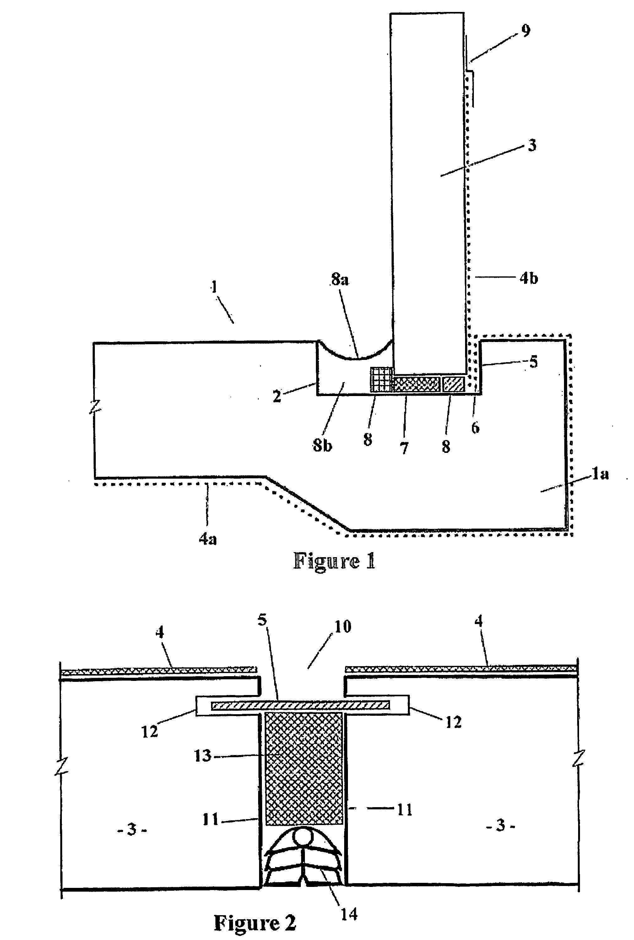
[0012] The building structure of the present invention may be of any useful type built on foundations as will be apparent to those skilled in the art. In particular, the building structure of the present invention is particularly suited for inground foundations where the ground level extends partway up the side walls of the building. The building structure of the present invention is also useful in applications where the foundations are made at or below the water table and wherein the building is exposed to penetration by groundwater.

[0013] The building structure may be of the type having peripheral footings upon which the external walls are located and which support a suspended timber flooring above the ground. Another type of building structure that may be constructed according to the present invention is a slab construction wherein an overground foundation in the form of a concrete slab is laid with an integral peripheral footing. Such slab constructions are particularly advanta...


PUM


Abstract

A building structure comprising a footing (21b), wherein the footing (21b) includes a channel (23), and at least one panel (24), wherein the panel (24) is located within said channel (23), wherein the footing (21b) is disposed on a waterproofing membrane (22) which membrane extends along side walls of the footing (21b) and into said channel (23) and wherein the panel (24) has an external waterproofing membrane (25) that is in waterproof engagement with the membrane of the footing (21b) in the channel (23) and wherein the waterproofing membranes (22, 25) comprise an absorptive clay disposed between water permeable layers.

Description

TECHNICAL FIELD [0001] The present invention relates to a building structure and to a method of forming a building structure, in particular to a building structure and method that provides improved waterproofing properties in the building structure. BACKGROUND ART [0002] Larger structures which are built on inground foundations are notoriously difficult to waterproof and current procedures that are used to provide waterproofing require peripheral excavation which are time consuming and costly and depending on site conditions, may restrict economic use of a site. [0003] In addition, excavations for inground foundations often are made at or below the water table which increases the need or an efficient means of waterproofing same. [0004] We have now found a building structure and a method of forming a building structure which increases land use efficiencies and provides improved waterproofing. [0005] Further objects and advantages of the present invention will become apparent from the...

Claims


Application Information

Patent Timeline
IPC IPC(8): E02D29/16E02D31/02E04B1/00E04B1/66
CPCE02D31/02E04B1/66E04B1/0007E02B3/16E02D19/16E02D29/16E02D31/00E04B1/70
Inventor LYDEN, PAUL JOHN
Owner LYDEN PAUL JOHN
Learn More