
Multi-spot optical fiber endophotocoagulation probe

a multi-spot, endophotocoagulation technology, applied in the direction of instruments, lighting and heating equipment, optical elements, etc., can solve the problems of significantly more expensive than traditional systems, time-consuming and laborious single-shot “step and repeat” approach, and putting patients at risk

Active Publication Date: 2007-11-15
IRIDEX CORP
View PDF24 Cites 74 Cited by
  • Summary
  • Abstract
  • Description
  • Claims
  • Application Information

AI Technical Summary

Problems solved by technology

This single-shot “step and repeat” approach is time consuming and tedious for the physician.
The lengthy duration of the anesthesia required by the procedure, and the number of shots delivered, can put the patient at risk.
However, there are potential problems with this approach.
This is significantly more expensive than traditional systems, and there are limits to the amount of power that can be coupled into a specific fiber diameter and numerical aperture.
There are also safety issues.
If for some reason the components that separate the energy fail or are partially damaged then non-uniform energy will be delivered through the multi-fiber bundle.
In the worst case, all the energy could be transmitted down a single fiber, and could result in significant over-treatment at one target tissue location.

Method used


Image

  • Multi-spot optical fiber endophotocoagulation probe
  • Multi-spot optical fiber endophotocoagulation probe
  • Multi-spot optical fiber endophotocoagulation probe

Examples


Embodiment Construction

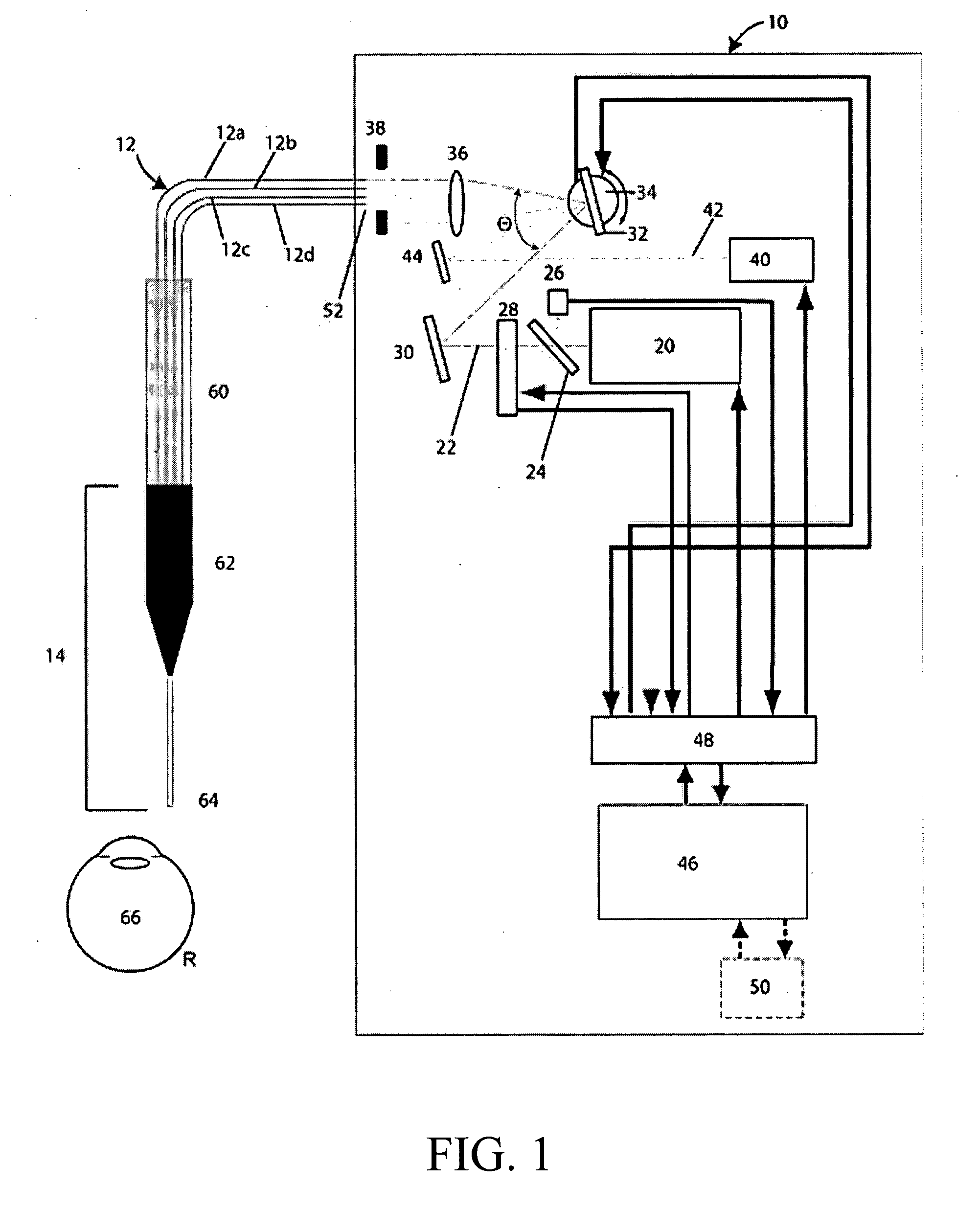
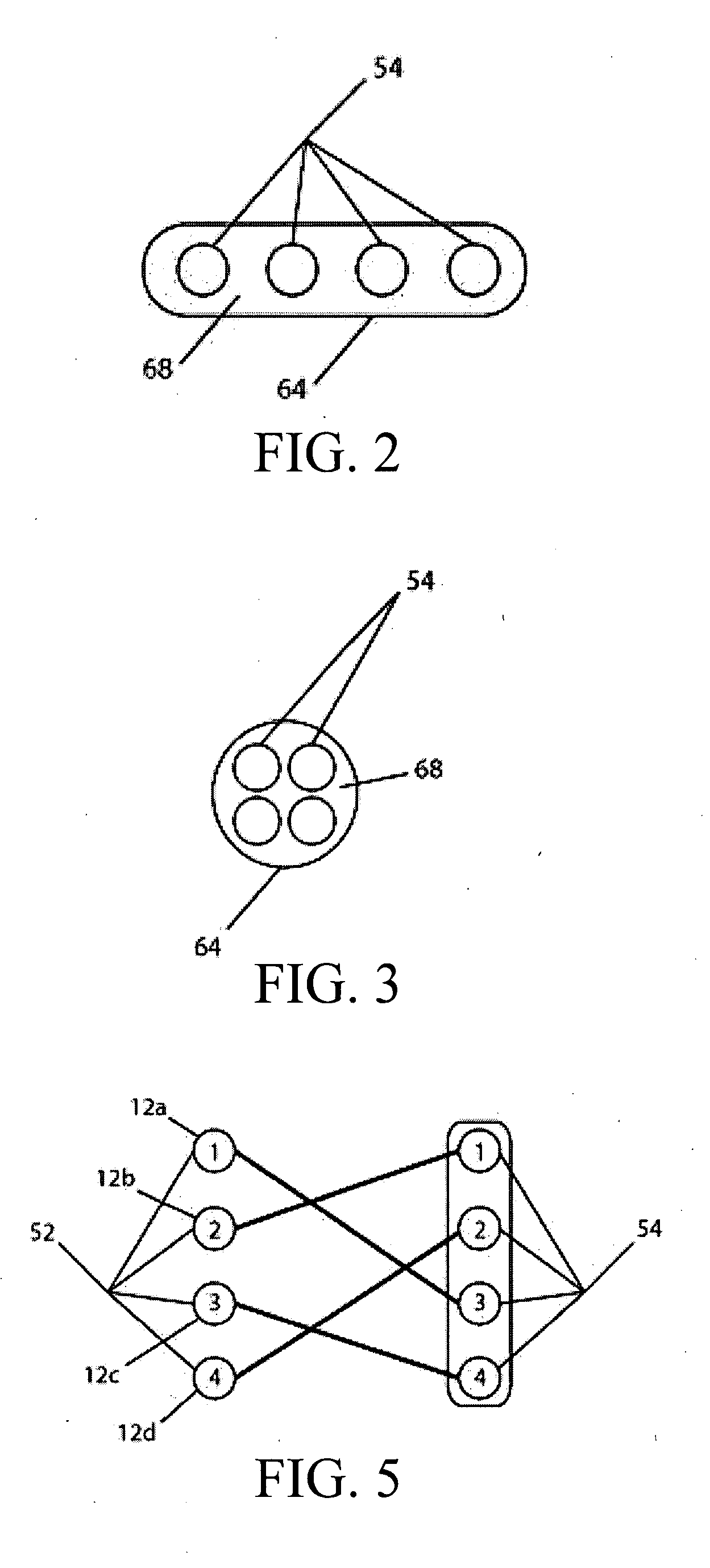
[0024] The invention is a system and technique for automatically and sequentially delivering multiple spots of laser energy through a multi-fiber endophotocoagulation probe. A moving mirror or fiber switch is used to sequentially deflect light into separate input ends of individual optical fibers, to ultimately provide a sequential pattern of spots at the target tissue by switching between the individual fibers. An exemplary photothermal treatment system is schematically shown in FIG. 1, and includes a light generating unit 10, an optical fiber bundle 12, and an endophotocoagulation probe 14.

[0025] Light generating unit 10 includes a light source 20 that generates a treatment beam of light 22. Light source 20 can be any conventional source of visible or invisible light, such as lasers, laser diodes, flash lamps, light emitting diodes, etc. Beam 22 first encounters a mirror 24, which serves to reflect a small amount of the beam 22 to a photodiode 26 for measuring the intensity of be...


PUM


Abstract

A system and method for treating target tissue including a light source for generating a beam of light, a plurality of optical fibers, a deflection device configured to selectively deflect the light beam into the input ends of the optical fibers, one optical fiber input end at a time, and a probe having a tip with the output ends of the optical fibers and configured for insertion into target tissue. The probe tip is configured to sequentially project spaced apart spots of the light beam from the output ends as the deflection device deflects the light beam into the optical fibers. One or more moving or static deflecting optics at the probe tip can be used to statically or dynamically deflect the beam exiting the optical fibers.

Description

[0001] This application claims the benefit of U.S. Provisional Application No. 60 / 785,552, filed Mar. 24, 2006.FIELD OF THE INVENTION [0002] The present invention relates to photothermal treatment of retinal tissue using fiber-optic-based endophotocoagulation probes. BACKGROUND OF THE INVENTION [0003] Laser photocoagulation procedures used to treat retinal tears, diabetic retinopathy, and other retinal disorders are well known and widely used. There are essentially three main delivery devices utilized for the delivery of laser energy: the slit lamp, the laser indirect opthalmoscope and the laser endophotocoagulation probe. The present invention deals with the latter. [0004] Traditional ophthalmic surgical laser systems include a laser source connected to a single core, optical fiber endophotocoagulation probe. The probe is inserted into the eye, allowing for the delivery of spots of laser energy to the target tissue, one spot at a time. Each laser pulse is activated by the depressio...

Claims


Application Information

Patent Timeline
IPC IPC(8): A61B18/22H01S3/10
CPCA61B2018/00636A61B2018/2211A61F2009/00897A61F9/00821A61F2009/00863A61F9/008
Inventor MORDAUNT, DAVID H.ANDERSEN, DAN E.
Owner IRIDEX CORP
Learn More