
Stopper structure for engine mount

a technology for stopping structures and engine mounts, applied in the direction of machine supports, shock absorbers, jet propulsion mountings, etc., can solve problems such as cracking or other defects, and achieve the effect of ensuring durability of the rubber stopper and the stopper structure, and high space utilization

Active Publication Date: 2007-11-15
SUMITOMO RIKO CO LTD
View PDF9 Cites 3 Cited by
  • Summary
  • Abstract
  • Description
  • Claims
  • Application Information

AI Technical Summary

Benefits of technology

[0018] It is therefore one object of this invention to provide a stopper structure for an engine mount for automotive vehicles, which is capable of exhibiting a sufficient durability, and a soft stopper performance, as well.

Problems solved by technology

Accordingly, the rubber stopper is less likely to suffer from or free from a stress-concentration at a local area pressed onto the laterally opposite edges of the first abutting plane of the rigid member, and a resultant cracking or other defects due to the stress concentration.

Method used


Image

  • Stopper structure for engine mount
  • Stopper structure for engine mount
  • Stopper structure for engine mount

Examples


Embodiment Construction

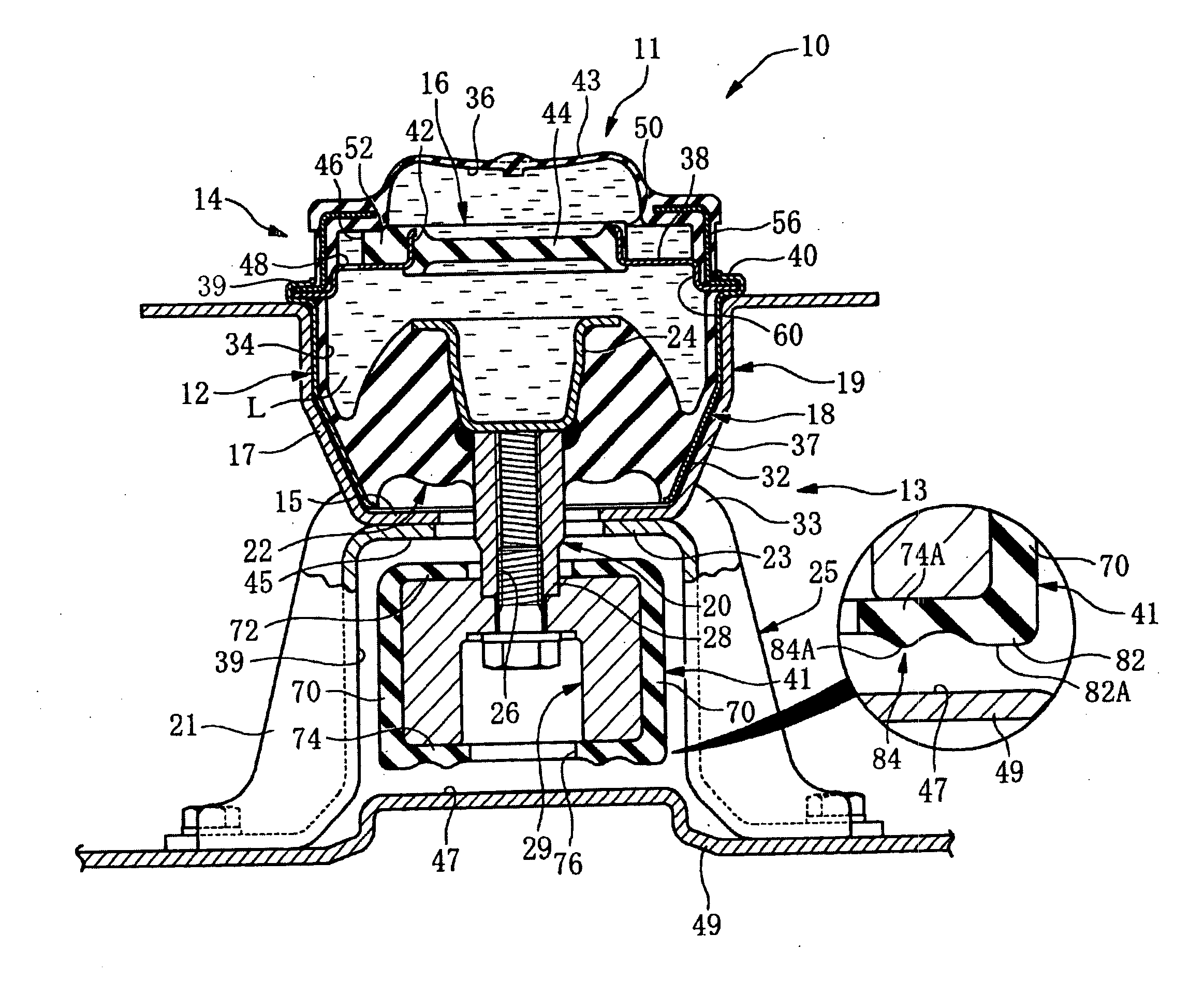
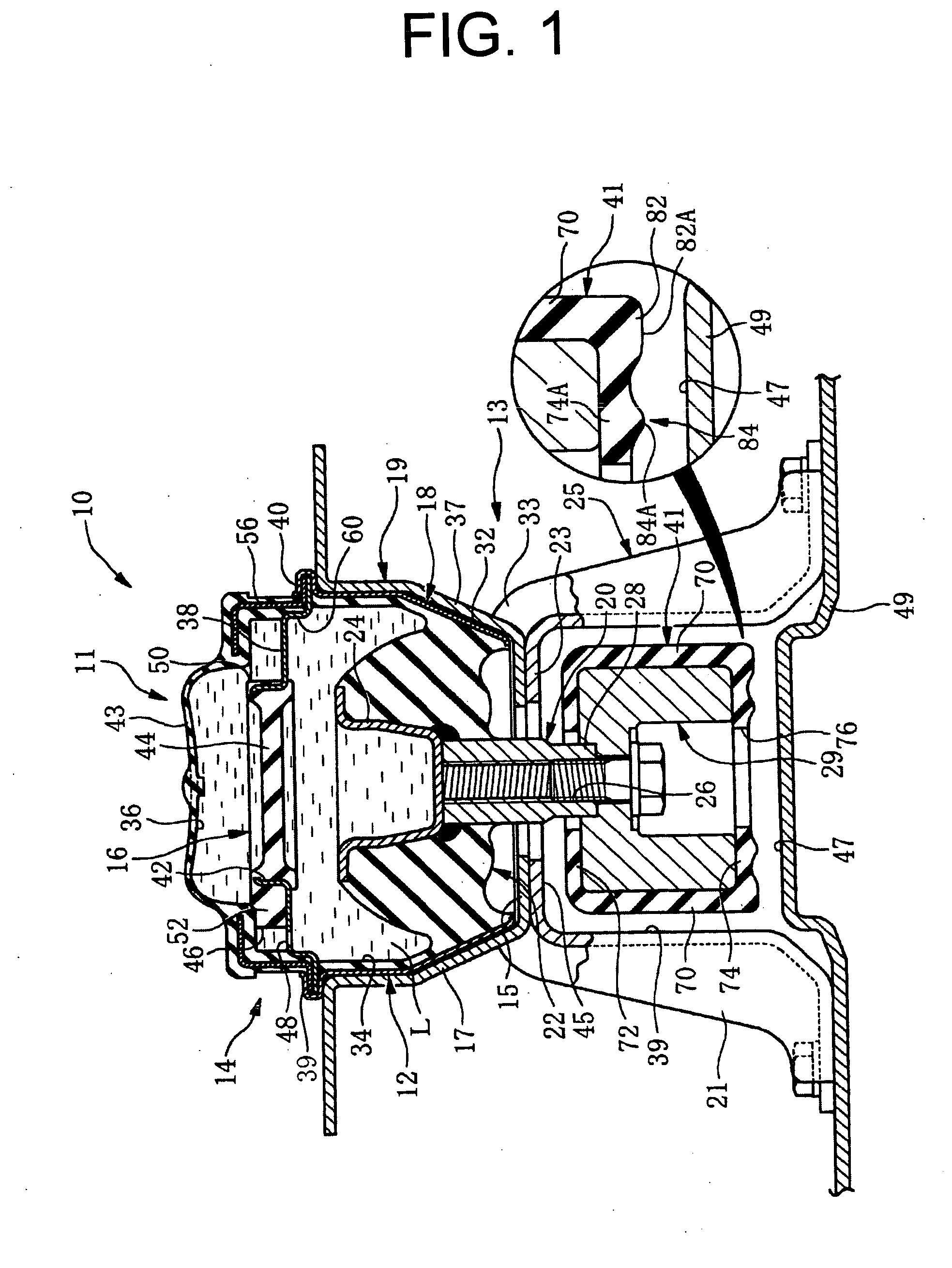
[0045] Referring first to FIGS. 1-3, there is shown a fluid-filled engine mount 10 of hanging type including a mount body 11, a mounting bracket 13 for mounting the mount body 11 on a body of the vehicle (not shown).

[0046] The mounting bracket 13 includes a holding portion 19 having a cup shaped part 17 and a bottom 15, and a fixing portion 25 having a pair of legs 21, 21 and a sheet 23 by which the legs 21, 21 are connected together, and on which the bottom 15 of the holding portion 19 is received. The holding portion 19 holds the mount body 11 in a press-fit manner, and the fixing portion 25 is fastened at distal ends of the legs 21, 21 to a member on the body side, e.g., a sub frame 49 of the vehicle.

[0047] An abutting member in the form of a connector arm 29 is a member disposed on a side of a power unit, and is inserted into a space 39 defined between the pair of legs 21, 21 and situated below the holding portion in an axis direction thereof. The connector arm 29 is connected...


PUM


Abstract

A stopper structure including: a rigid abutting member extending in its longitudinal direction with a rectangular cross sectional shape; and a rubber stopper having a base portion of tubular cross sectional shape and secured press-fit onto the rigid abutting member without being adhesive thereto, two peripheral projections formed on laterally opposite sides of a first abutting plane of the base portion and extending in the longitudinal direction, and a central projection formed on an intermediate area interposed between the peripheral projections of the first abutting plane of the base portion. The peripheral projections are situated above laterally opposite edges of a first abutting plane of the rigid abutting member, and have a width dimension extending inside and outside the laterally opposite edges. The central projection projects outward from the first abutting plane of the base portion with the same height as the peripheral projections.

Description

[0001] This application is a Continuation-in-Part of application Ser. No. 10 / 789,689 filed Feb. 27, 2004.INCORPORATED BY REFERENCE [0002] The disclosure of Japanese Patent Application No. 2003-055017 filed on Feb. 28, 2003 including the specification, drawings and abstract is incorporated herein by reference in its entirety. BACKGROUND OF THE INVENTION [0003] 1. Field of the Invention [0004] The present invention relates generally to stopper structures for engine mounts, more particularly to such a stopper structure in which a rubber stopper formed independently and secured press-fit onto an abutting member connected to one of two mounting members of an engine mount, without being adhesive to a superficial surface of the abutting member. [0005] 2. Description of the Related Art [0006] An engine mount has been widely used for elastically mounting or hanging a power unit of an automotive vehicle on or from a body of the vehicle in a vibration damping fashion. Generally, such an engine...

Claims


Application Information

Patent Timeline
Patent Type & Authority Applications(United States)
IPC IPC(8): F16F9/32F16F13/08B60K5/12F16F13/10
CPCF16F13/108F16F13/101
Inventor OKANAKA, TAKEHIROANDOU, TETSUJI
Owner SUMITOMO RIKO CO LTD
Learn More