Roller bearing apparatus, method of producing roller bearing apparatus and cover attached to roller bearing apparatus

a technology of roller bearings and roller bearings, which is applied in the direction of mechanical equipment, instruments, transportation and packaging, etc., can solve the problems of inability to accurately form the sensor mount of the prior art cover, the cap nut to be embedded in the cover is easily immobilized therein, and the form of the sensor mount may sink

Active Publication Date: 2006-10-12
JTEKT CORP
View PDF16 Cites 16 Cited by
  • Summary
  • Abstract
  • Description
  • Claims
  • Application Information

AI Technical Summary

Benefits of technology

[0014] In other words, the object of the present invention is to provide a roller bearing apparatus having improved sealing between the roller bearing and the cover to prevent muddy water from entering the interior and ensure durability and a method of producing the roller bearing apparatus.
[0016] Still another object of the present invention is to provide a roller bearing apparatus in which a cap nut is provided in a synthetic resin cover and the cap nut is used to fix the sensor to the flange for positioning the sensor with improved accuracy.
[0018] In the roller bearing apparatus having the above structure, the annular space is filled with sealant and, therefore, the sealant is interposed between the outer ring and the cover, which can close and seal the opening of the outer ring. The beveled part is conventionally formed in producing an outer ring. There is no need of additional processing, such as forming a groove, as required in the prior art. Consequently, a seal can be provided between the cover and the outer ring without a significant increase in cost.
[0030] In the roller bearing apparatus cover having the above structure and the roller bearing apparatus using this cover, the seating face of the sensor mount is formed on one of the inner and outer end faces of the partition and the ribs are provided to form specific recesses on one end face together with the sensor mount. Because of the recesses, the amount of synthetic resin on the end face is reduced, preventing the seating face of the sensor mount from being deformed due to thermal contraction of the synthetic resin in the course of producing the cover by molding.
[0032] In such case, the seating face can be formed with high accuracy without complicating a mold shape compared to the case where the sensor mount and ribs are provided separately. In the completed cover, the sensor mount is reinforced by the ribs, preventing the mounting geometry from being deformed.
[0034] In the third aspect of the present invention, the nut end face (the other axial end side end face) of a cap nut and the cover surface are not on one plane (not leveled), unlike the prior art. The nut end face of the cap nut is positioned on the other axial end side of the outer cover surface facing the sensor flange. Consequently, the flange of the sensor (sensor flange) is in contact with the nut end face of the cap nut, but substantially not in contact with the outer cover surface. Therefore, the sensor is less influenced by sinkage or warpage of the cover, preventing the sensor from tilting or dislocating.

Problems solved by technology

However, using a synthetic resin cover has the following problems.
However, in the synthetic resin cover, some forms of the sensor mount may sink (deform) as a result of thermal contraction of the synthetic resin in the course of molding, and the seating face of the sensor mount of the prior art cover will not be accurately formed, requiring post processing in order to use the seating face as a sensor-mounting reference level.
Further, the cap nut to be embedded in the cover is easily immobilized therein.
However, being made of a synthetic resin, the cover easily sinks or warps in the course of molding.
Therefore, when the flange is abutted to the cover, the sensor may be tilted or axially dislocated by the warpage of the cover, problematically deteriorating the sensor gap accuracy.

Method used


Image

  • Roller bearing apparatus, method of producing roller bearing apparatus and cover attached to roller bearing apparatus
  • Roller bearing apparatus, method of producing roller bearing apparatus and cover attached to roller bearing apparatus
  • Roller bearing apparatus, method of producing roller bearing apparatus and cover attached to roller bearing apparatus

Examples


Embodiment Construction

[0046] Embodiments of the roller bearing apparatus of the present invention, the method of producing the roller bearing apparatus, and the cover that is attached to the roller bearing apparatus are described hereafter with reference to the drawings.

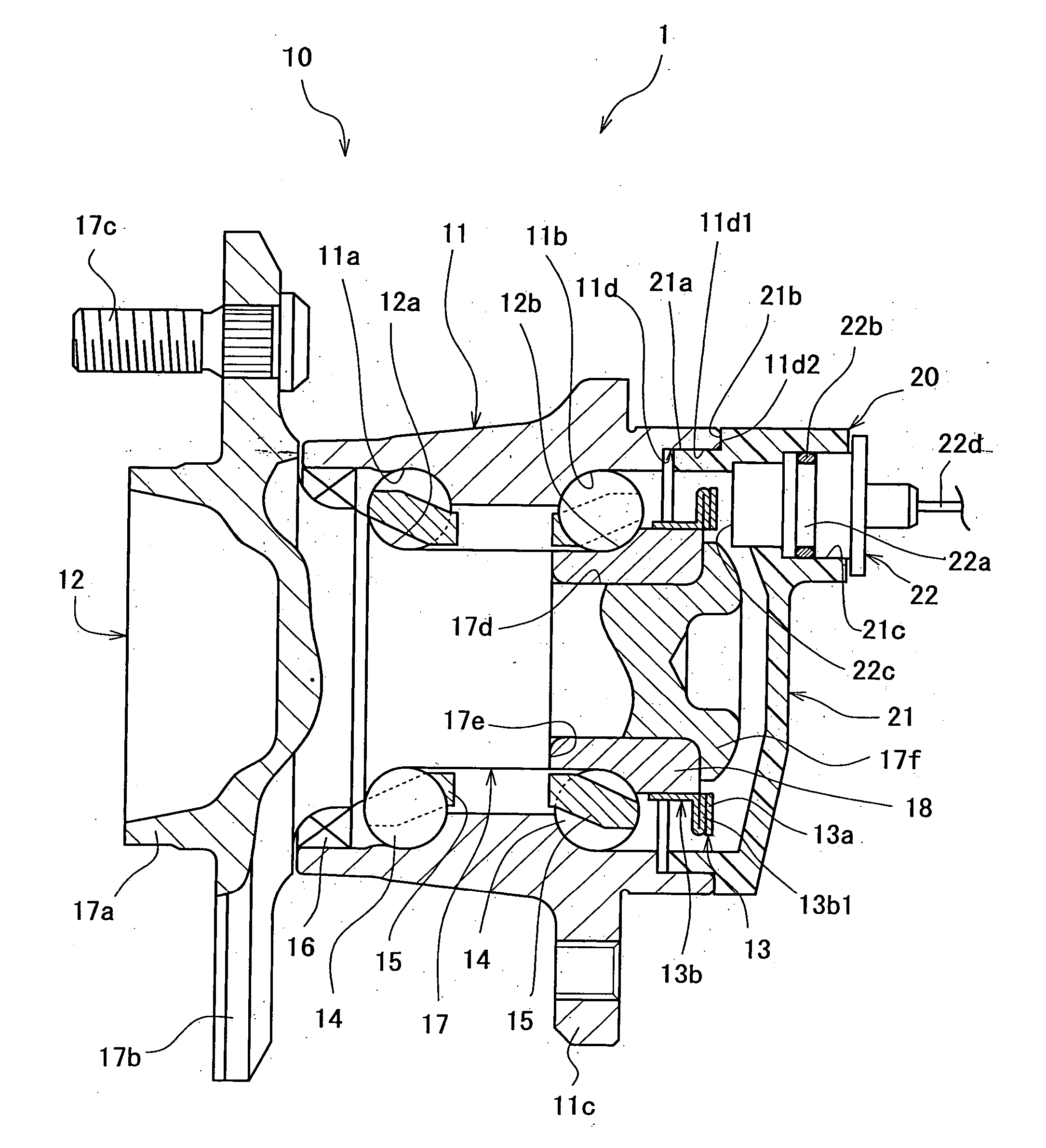
[0047]FIG. 1 is an axial cross-sectional view showing the structure of a roller bearing apparatus (wheel bearing apparatus) according to a first aspect of the present invention. A wheel bearing apparatus 1 is used to rotatably support a wheel of a vehicle such as a car. The wheel bearing apparatus 1 comprises a roller bearing 10 that supports a wheel of a vehicle to which the wheel bearing apparatus 1 is attached and a cover 20 that closes the roller bearing 10 at one end.

[0048] First, the roller bearing 10 is described. The roller bearing 10 is a double-row angular ball bearing, comprising an outer ring 11 as a fixed ring, an inner ring 12 as a rotary ring, an encoder 13 attached to the inner ring 12, multiple balls 14 as rolling eleme...


PUM


Abstract

A roller bearing apparatus provided with a roller bearing having an outer ring with a cylindrical opening that opens at one end and a cover fitted in the opening against the inner periphery thereof to close it. The cover is provided with an inscribing surface that inscribes the. inner periphery of the opening and a stepped surface that protrudes radially outward from the inscribing surface to abut the axial end face of the opening. The axial end face of the opening is provided with a beveled part on the inner rim. An annular space formed by the beveled part, inscribing surface, and stepped surface is filled with sealant.

Description

BACKGROUND OF THE INVENTION [0001] The present invention relates to a roller bearing apparatus, a method of producing the roller bearing apparatus, and a cover attached to the roller bearing apparatus. [0002] Some roller bearing apparatuses that support wheels, for example, of vehicles are provided with a rotation number detector that detects the rotating speed of the wheel for controlling the anti-lock brake system and the like. Such roller bearing apparatuses are provided for example, as shown in FIG. 11, with a roller bearing comprising an inner ring 51 as a rotary ring that co-rotates with a flange 50 to which a wheel is attached and an outer ring 52 that interposes multiple rolling elements between itself and the inner ring 51 and is attached to a vehicle body, and a closed-end cylindrical cover 54 attached to the outer ring 52 and carrying a rotation number detector 53 that detects the rotation number of a wheel. An end 54a of the cover 54 is fitted in the outer ring 52 agains...

Claims


Application Information

Patent Timeline
IPC IPC(8): F16C41/04
CPCB60B27/0005B60B27/0068B60B27/0073B60B27/0084B60B27/0094F16C19/186F16C33/783G01P1/00G01P1/026G01P3/443F16C41/007F16C2326/02F16C33/723
Inventor NAGATA, SYUJINISHIYAMA, TOMONARIDEGUCHI, MASARU
Owner JTEKT CORP
Why Eureka
Try Eureka