
Wide dynamic range image sensor and method of use

a wide dynamic range, image sensor technology, applied in the field of imaging devices, can solve the problems of low dynamic range degrading the quality of outdoor images, reducing the accuracy of image acquisition operation, and difficulty in providing simultaneously wide dynamic range and very low noise in image sensor arrays, so as to improve the final image quality, wide dynamic range, and accurate image acquisition operation

Inactive Publication Date: 2007-11-15
RE SECURED NETWORKS LLC
View PDF3 Cites 23 Cited by
  • Summary
  • Abstract
  • Description
  • Claims
  • Application Information

AI Technical Summary

Benefits of technology

[0018]As described more fully below, an innovative image sensor is provided that has significantly wider dynamic range, yielding a more accurate image acquisition operation, ultimately resulting in an improved final i

Problems solved by technology

It has been difficult to provide simultaneously wide dynamic range and very low noise in image sensor arrays.
Present trends towards small pixel pitches in CMOS four-transistor (4T) technology result in loss of charge capacity as the pixel shrinks.
This low dynamic range degrades the quality of outdoor images because there is simply not enough range in the sensor photodiode to describe both the bright and dark areas of the scene.
However, the performance of conventional CMOS image sensors suffers from a number of problems.
For example, conventional CMOS image sensors suffer from noise associated with the process for resetting the photodiode in each pixel to a known potential after each exposure and in preparation for the next image.
This noise, also referred to as reset noise or KTC noise, is often a significant source of noise in camera systems employing conventional CMOS image sensors.
Reducing the capacitance of the sense node can reduce reset noise, but results in a corresponding reduction in the total charge that can be collected and therefore undesirably reduces the overall dynamic range in the camera system.
Moreover, the trend towards small pixel pitches in image sensors results in additional loss of charge capacity, further reducing dynamic range.
Low dynamic range significantly degrades image quality, particularly in outdoor images, due to the limited range of the sensor's photodetector and its inability to describe both bright and dark areas of the scene in a single frame exposure.
However, the significantly increased costs associated with additional frame buffers renders this approach impractical for many applications.
However, in low light situations, the higher noise floor and higher dark current of the 3T pixel result in greatly degraded performance compared to 4T pixels.
However, the required buffer memory cost is comparable to the cost of the image sensor, and this cost is not easily borne by low-end consumer applications, such as cellular phone cameras.
This lower noise floor results and the lack of significant dark signal noise results in three to four times improvement in low light performance when compared to 3T technology.
However, the total dynamic range remains at 56 dB, and outdoor images are inferior to larger pixel cameras.

Method used


Image

  • Wide dynamic range image sensor and method of use
  • Wide dynamic range image sensor and method of use
  • Wide dynamic range image sensor and method of use

Examples


Embodiment Construction

[0023]The present invention is directed to a wide dynamic range image sensor and method of use. The following description contains specific information pertaining to the implementation of the present invention. One skilled in the art will recognize that the present invention may be implemented in a manner different from that specifically discussed in the present application. Moreover, some of the specific details of the invention are not discussed in order to not obscure the invention. The specific details not described in the present application are within the knowledge of a person of ordinary skill in the art.

[0024]The drawings in the present application and their accompanying detailed description are directed to merely exemplary embodiments of the invention. To maintain brevity, other embodiments of the invention which use the principles of the present invention are not specifically described in the present application and are not specifically illustrated by the present drawings....


PUM


Abstract

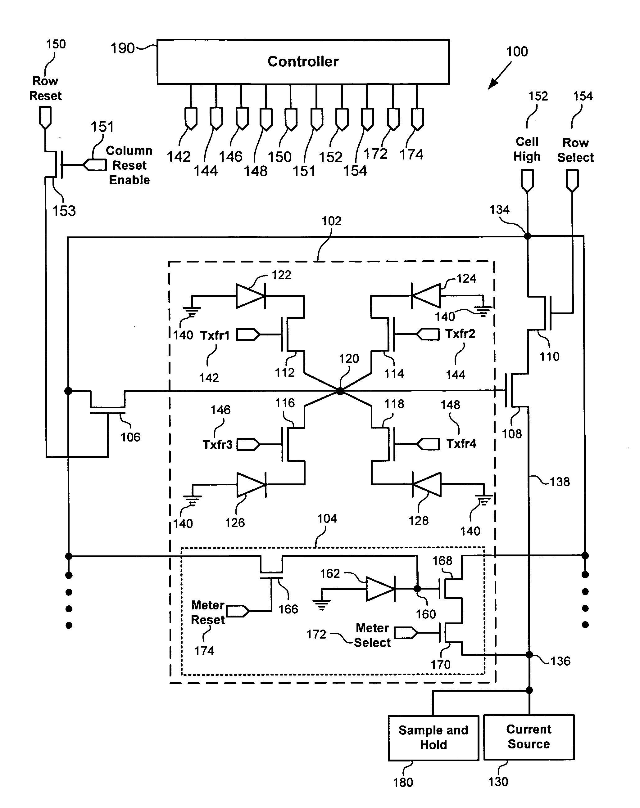
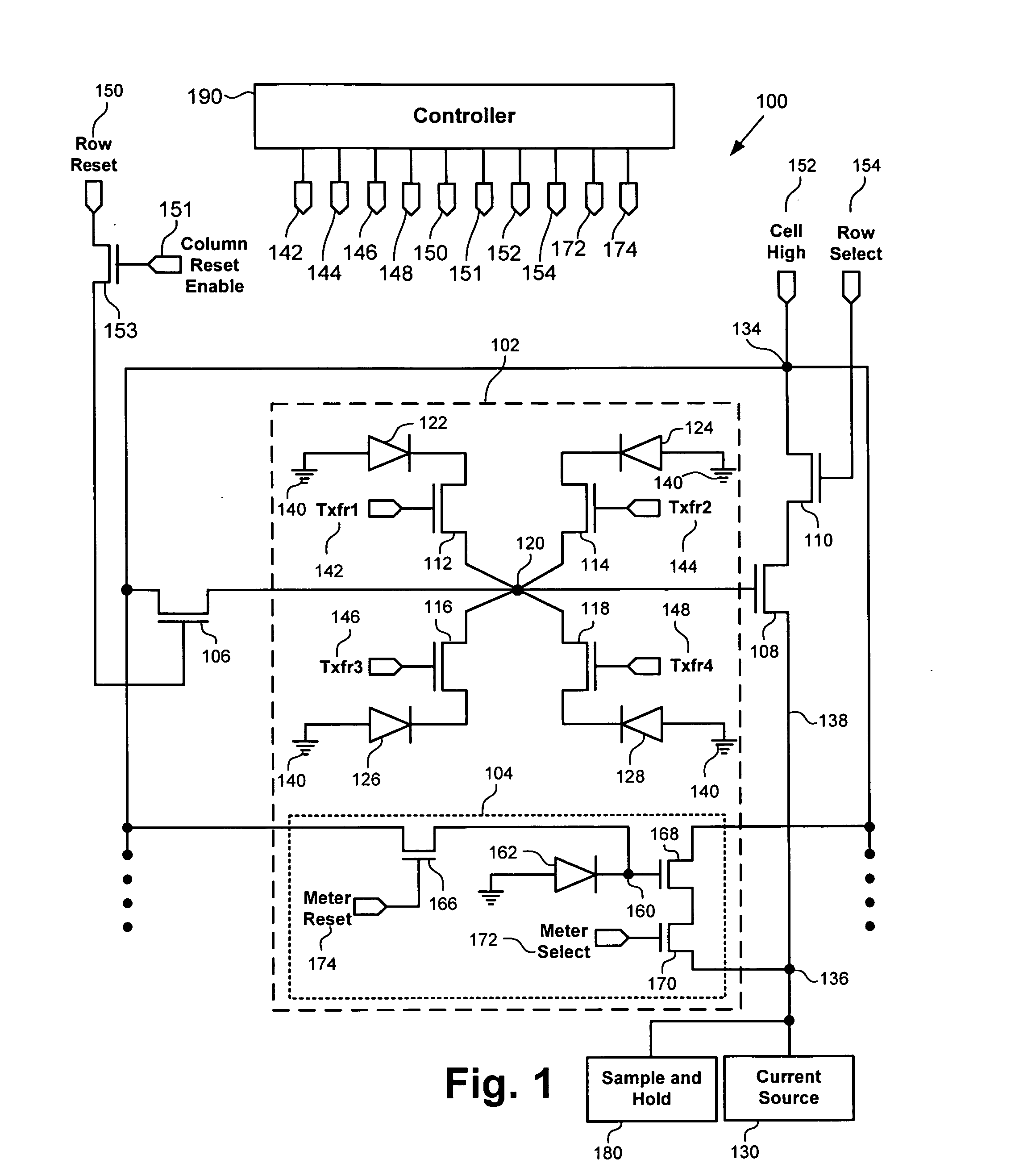
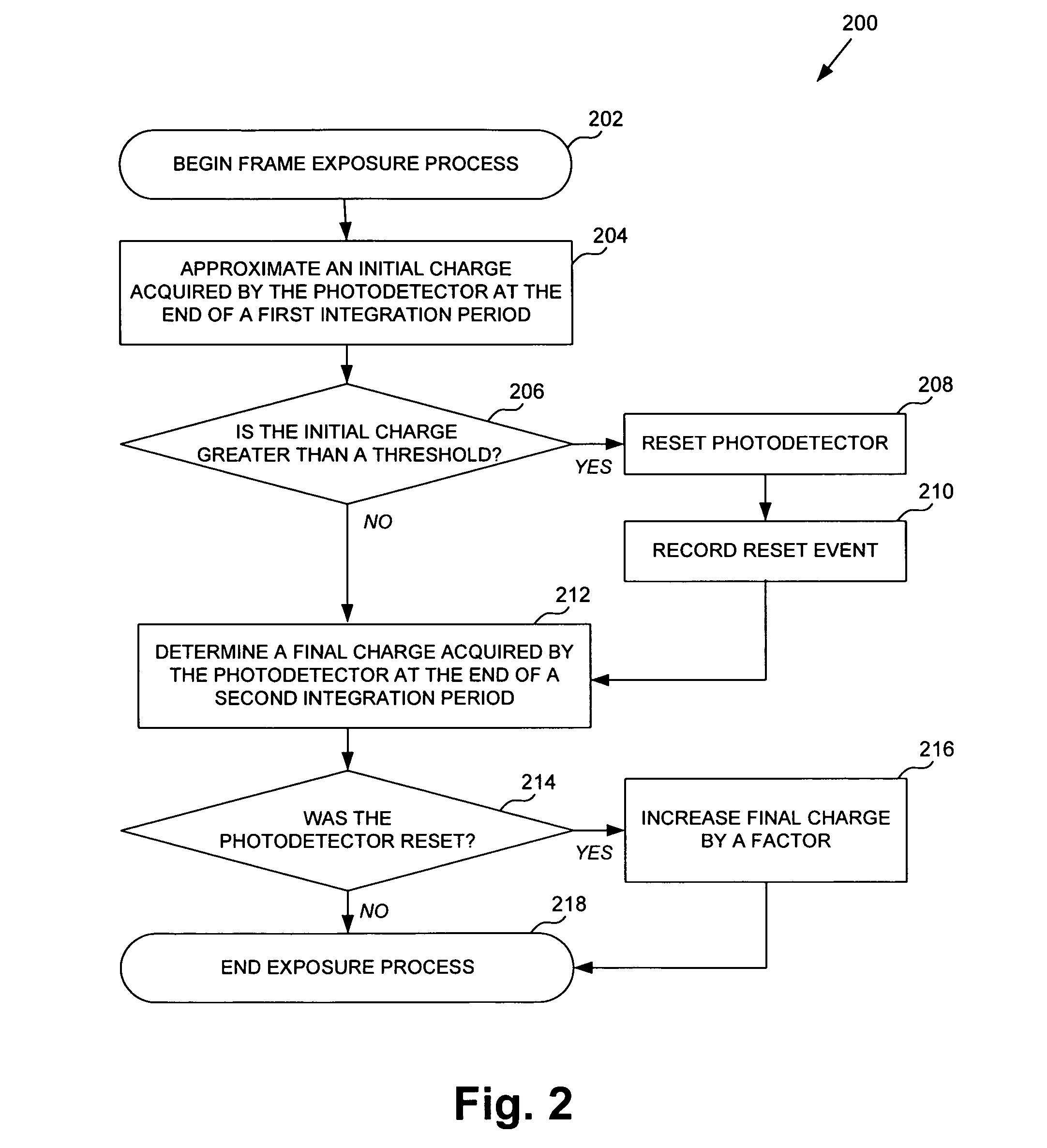
An exemplary image sensor comprises a photodetector proximate to a pixel site, and a light meter proximate to the pixel site configured to approximate an initial charge acquired by the photodetector at the end of a first integration period of a frame exposure period. A reset circuit resets the photodetector if the approximated initial charge acquired by the photodetector exceeds a threshold. A readout circuit detects a final charge acquired by the photodetector at the end of a second integration period of the frame exposure period. If the photodetector was reset, the readout circuit adjusts the final exposure to account for exposure prior to the photodetector having been reset.

Description

[0001]The present application claims the benefit of and priority to a pending provisional patent application entitled “Wide Dynamic Range CMOS Image Sensor Circuit and Method of Use,” Ser. No. 60 / 800,129 filed on May 12, 2006. The disclosure in that pending provisional application is hereby incorporated fully by reference into the present application.BACKGROUND OF THE INVENTION[0002]1. Field of the Invention[0003]The present invention is generally in the field of imaging devices. More specifically, the invention is in the field of imaging devices having improved dynamic range.[0004]2. Background Art[0005]Image sensors have broad applications in many areas. Image sensors convert a received image into representative information indicative of the received image. Examples of image sensors include solid-state image sensors, such as charge coupled devices (CCDs) and CMOS imaging devices (also known as CMOS image sensors), among others.[0006]Image sensors are fabricated from semiconductor ...

Claims


Application Information

Patent Timeline
IPC IPC(8): H01L27/00H04N5/353H04N5/355H04N5/374H04N5/378
CPCH04N5/37457H01L27/14643H04N25/778
Inventor MANN, RICHARD A.
Owner RE SECURED NETWORKS LLC
Learn More