
Single piece dual coating reflector recessed wall wash luminaire

a dual-coating, recessed wall wash technology, applied in the field of single-piece dual-coating reflector recessed wall wash luminaire, can solve the problems of difficult to achieve proper, fail to blend architecturally into the overall desires of the space, and instruments designed to disguise themselves are much harder to develop, so as to achieve superior illumination qualities of uniformity and improve energy efficiency

Inactive Publication Date: 2007-11-08
INTENSE LIGHTING
View PDF12 Cites 20 Cited by
  • Summary
  • Abstract
  • Description
  • Claims
  • Application Information

AI Technical Summary

Benefits of technology

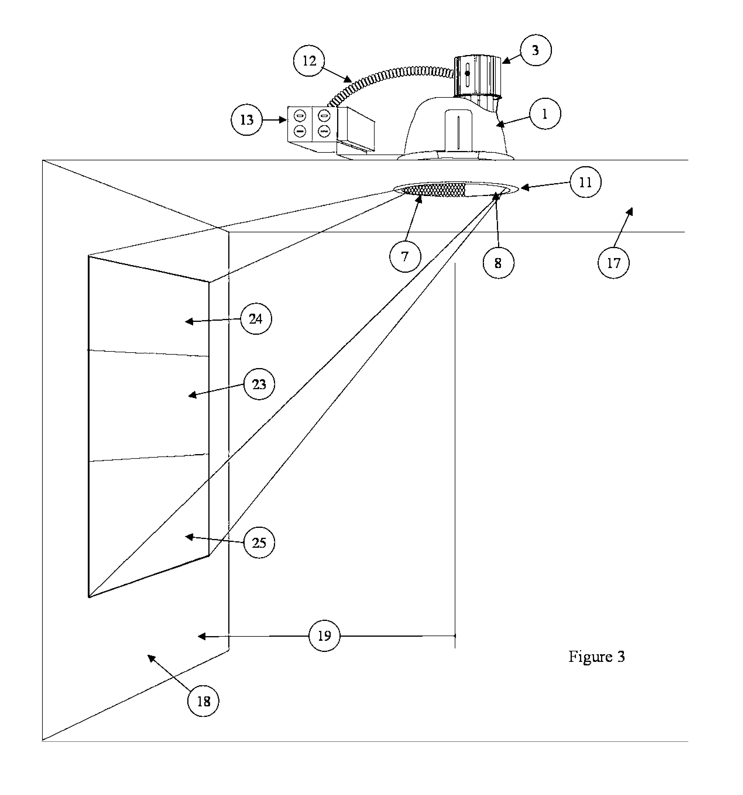
[0019] The invention provides vertical illumination or wall washing adjacent to its recessed mounting, preferred in the ceiling; with proper set back distances from the vertical surface or wall and may match the exposed appearance to other common recessed down lights within the same environment. The optical design utilizes a unique single piece cone shape reflector, design with dual internal finishes or coatings, a lamp socket assembly offset from center with the lamp in the vertical position in the preferred embodiment, and the socket in the upper position to achieve superior illumination qualities of uniformity, while additionally providing improved energy efficiency over other prior art.
[0020] The single piece reflector has dual finish coatings divided in two (2) one hundred and eighty (180) degree internal areas specifically located in regards to the lamp to perform functions required by this system. The specular or highly reflective area of the reflector, with its mid point directly behind the center of the lamp extending ninety (90) degrees in each direction, provides direction of light at maximum efficiency towards the vertical surfaces adjacent to its mounting increasing the performance of the system. The diffused or matte area of the reflector, is opposite that of the specular area, provides brightness control and minimizes flash or cone brightness at the uncomfortable and visible high angles to persons within the space below.
[0022] One example of a unique situation may occur with a structural column within the environment where the physical width may require a narrower distribution of light from the reflector and increased brightness control for persons within the space. This may be accomplished by decreasing the width of the specular portion of the reflector and increasing the width of the matte area. Another example occurs where two (2) adjacent walls intersect and it is desired to light each wall, including the corner intersection uniformly. This may be accomplished by increasing the width of the specular portion and decreasing the matte area within the reflector. It is recognized that having either finish narrower than ninety (90) degrees or more than two hundred seventy (270) degrees minimizes the effectiveness of this invention.
[0023] The position of the lamp is offset from the center of the reflector purposely positioned to achieve optimal performance of the lamp source and to enable best use of highly specular portion of the reflector. This creates superior efficiency as compared to a centered lamp utilized by prior art and allows wider light distribution which provides better uniformity. The offset lamp position provides illumination spread much higher and lower on the vertical surface than centered lamp systems in prior art to provide not only a more uniform light distribution but also higher levels of illumination. In addition, the offset position of the lamp provides better shielding of the lamp source and thus achieves superior visual comfort. The lamp socket assembly is field adjustable to provide “fine-tuning” by persons skilled in the art of installation. In addition, the offset lamp placement allows for easier maintenance and less chance of breaking the lamp, as well as allows for easier orientation of the fixture as offset side is always positioned away from the vertical surface to be illuminated.

Problems solved by technology

In the field of lighting, wall washing or the art of illuminating a vertical surface is common, but is often difficult to achieve proper results.
Some have achieved satisfactory results of the illumination task, but fail to blend architecturally into the overall desires of the space.
Instruments designed to disguise themselves are much harder to develop, often less efficient and much harder to achieve proper results, but have the ability to perform their task without the lay person recognize them.
Over time this method was seen as too inefficient and could be seen by the lay person as a different device, undesired by persons skilled in the art.
Additional prior patents similar to Neil, U.S. Pat. No. 6,994,456 use offset lamping to redirect light, but are not symmetrical and therefore do not resemble other standard symmetrical down lights within the same area.

Method used


Image

  • Single piece dual coating reflector recessed wall wash luminaire
  • Single piece dual coating reflector recessed wall wash luminaire
  • Single piece dual coating reflector recessed wall wash luminaire

Examples


Embodiment Construction

[0032]FIG. 1, the wall washer fixture is shown as it would appear prior to installation as people skilled in the art would receive it from the manufacture. The preferred embodiment shown is designed for a vertically mounted fluorescent lamp 2 positioned in the one-piece reflector 1. Other lamp sources may be used to achieve similar characteristics mounted in the same location and in the same fashion. The separate lamp socket assembly 3 is attached to the one-piece reflector 1 by use of tool-less fasteners (FIG. 4-20). The lamp socket is made from light weight metal or other man-made material and designed with heat fins 4 to dissipate heat generated by the lamp source 2. A slide mount adjustment 9 allows the lamp to positioned higher or lower by those skilled in the art during installation per manufacturers instructions. The reflector 1, lamp source 2, and lamp socket assembly 3 are secured to a support frame or chassis 10 and held in place by fasteners. The reflector 1 and lamp sour...


PUM


Abstract

A recessed ceiling mounted luminaire with a single piece, dual finish coating reflector designed to evenly illuminate vertical surfaces without the use of a lens medium, such as interiors walls of a building, utilizing vertical lamp sources mounted on a common down light frame and giving a common down light exterior visual appearance from the space below. Current art utilized modified downlight reflectors with an additional kicker reflector added to redirect only a portion of available light accordingly. This invention combines lessons learned by previous art with the ability to complete the task by using a single reflector design with added efficiency. This adds advantages not previously seen in this area of expertise including higher energy efficiency with better uniformity on all areas of the vertical surfaces.

Description

TECHNICAL FIELD OF THE INVENTION [0001] A lighting system for illuminating vertical surfaces in building interiors. BACKGROUND OF THE INVENTION [0002] In the field of lighting, wall washing or the art of illuminating a vertical surface is common, but is often difficult to achieve proper results. Instruments of illumination have been developed and used to accomplish this task for many decades. Some have achieved satisfactory results of the illumination task, but fail to blend architecturally into the overall desires of the space. [0003] It is recognized by persons skilled in the art that applying proper illumination to vertical surfaces of a space such as walls of a corridor or small room can visually extend the perceived distance to that surface, thus creating the illusion of greater area within the space. Common areas of this exercise are conference rooms, corridors, offices, living spaces, or other locations where the perception of size is desired. [0004] In this exercise, people ...

Claims


Application Information

Patent Timeline
IPC IPC(8): F21S8/00
CPCF21V7/09F21S8/02F21S8/026
Inventor GRAY, ALLAN
Owner INTENSE LIGHTING
Learn More