
Image Transmission System and Image Transmission Method

Active Publication Date: 2007-11-08
PANASONIC CORP
View PDF14 Cites 80 Cited by
  • Summary
  • Abstract
  • Description
  • Claims
  • Application Information

AI Technical Summary

Benefits of technology

[0021] According to an image transmission system of the present invention, a display position, an area to which a display image is transmitted and the like are adjusted in a PC and then the display image is transmitted from the PC to a projector. Therefore, it is possible for a user to select a full-screen display, a two divided-screen display or a four divided-screen display for projecting a PC display image onto the projector screen. Moreover, it is possible to select an area to be transmitted to the projector and to project a display image in the selected area onto the projector screen, and thus the various types of presentations can be implemented. In addition, the size of the display image to be transmitted is adjusted, in the PC, to the display size to be projected onto the projector screen, and then the adjusted display image is transmitted to the projector, so that the transmission load can be reduced.
[0022] In addition, the resolution of the display image to be transmitted is adjusted in the PC in accordance with the resolution that the projector can support, and then the adjusted display image is transmitted to the projector, so that the amount of the transmission between the PC and the projector can be reduced.
[0023] Furthermore, a compression degree of the display image is adjusted and then the adjusted display image is transmitted to the projector, so that it is possible to transmit the display image in accordance with the user setting such as picture quality priority, transmission speed priority and the like.

Problems solved by technology

However it is bothersome that a user needs to connect the PC and the projector each time, moreover in the case where, for example, the data to be projected are stored in plural PCs separately, the PC and the projector requires to be reconnected.

Method used


Image

  • Image Transmission System and Image Transmission Method
  • Image Transmission System and Image Transmission Method
  • Image Transmission System and Image Transmission Method

Examples


Embodiment Construction

[0099] Hereafter, the best mode for carrying out the present invention is explained in detail.

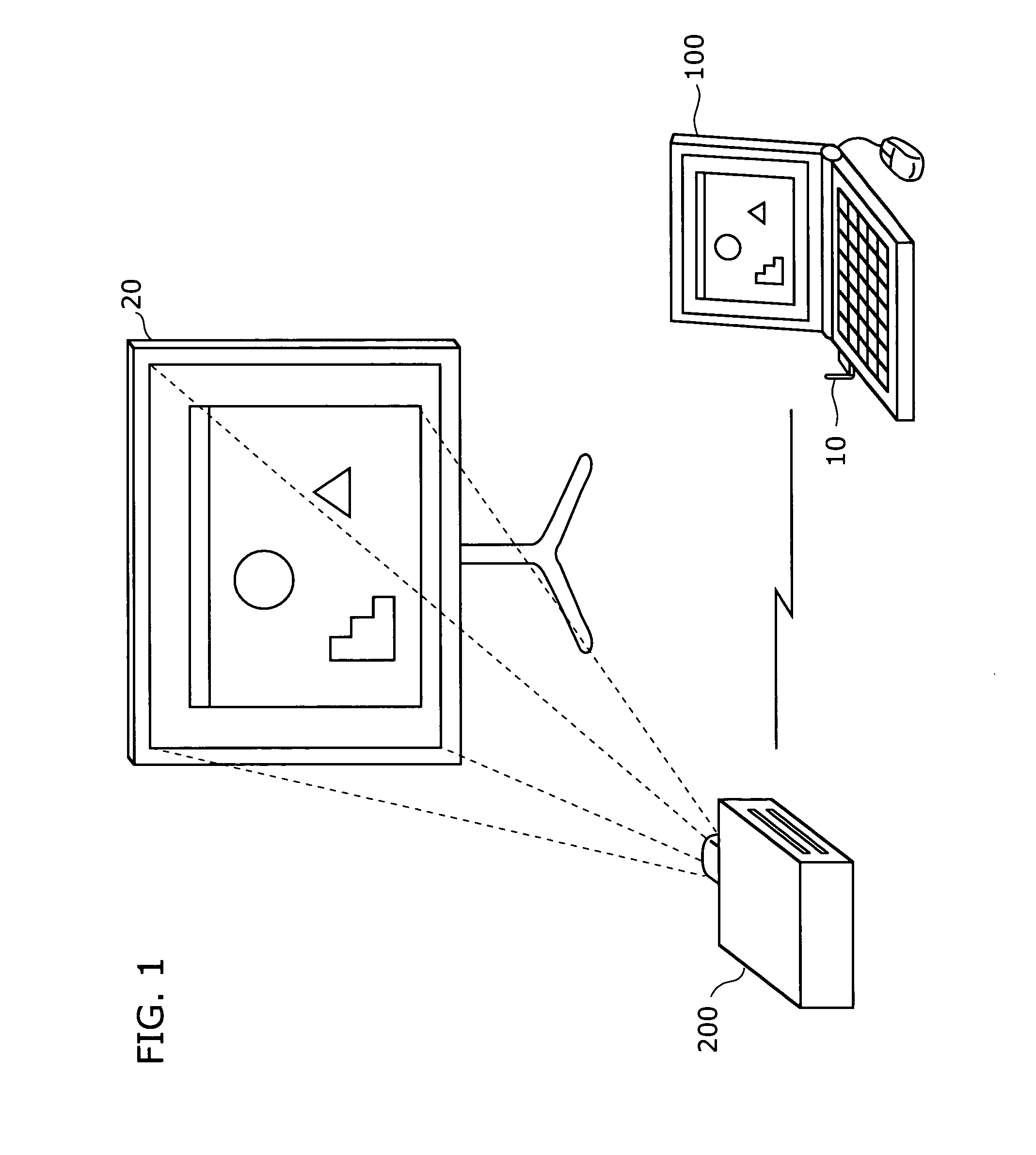
[0100]FIG. 1 is a drawing showing an external view of an image transmission system for an embodiment of the present invention.

[0101] The image transmission system transmits an image displayed on a PC 100 from the PC 100 to a projector 200, and then the received display image is projected onto a screen 20 by the projector 200. The PC 100 is equipped with a wireless LAN card 10 storing a wireless LAN chip so as to transmit an image signal to the projector 200 through a network.

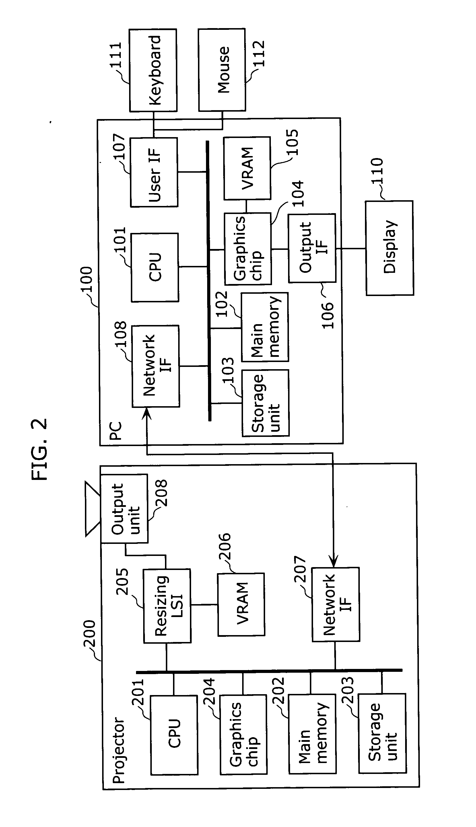
[0102]FIG. 2 is a block diagram showing a hardware configuration of the PC 100 and the projector 200 included in the image transmission system for the present embodiment.

[0103] As shown in FIG. 2, the PC 100 has a CPU 101, a main memory 102, a storage unit 103, a graphics chip 104, a VRAM 105, an output IF 106 to output onto a display 110, a user IF 107 to obtain an instruction signal based on a user's operation fro...


PUM


Abstract

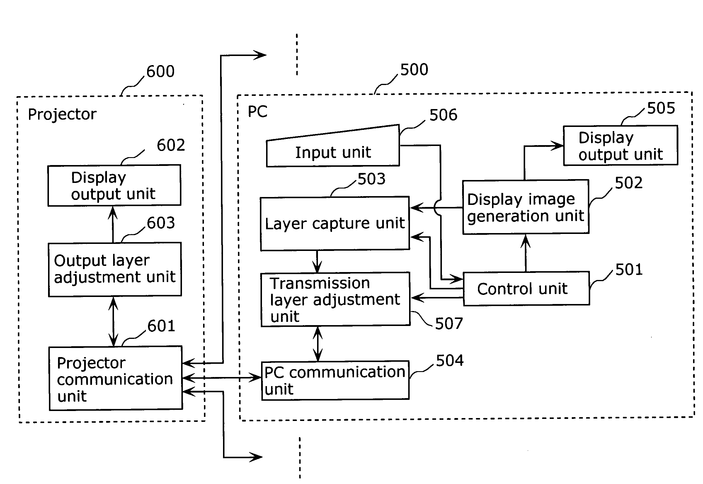
An image transmission system which enables to perform various types of presentations and also to reduce a transmission path is provided. A PC (500) includes a display image generation unit (502), a layer capture unit (503) for sorting a layer composing a display image into a layer to be transmitted to a projector (600) and a layer not to be transmitted, transmission layer adjustment unit (507) for performing adjustment on the captured layer, and a PC communication unit (504) for transmitting the adjusted layer to the projector (600), the projector (600) includes a determines adjustment description put for a projector communication unit (601) for receiving a transmission layer, an output layer adjustment unit (603) for determining the content of the adjustment performed on the received layer and readjusting the received layer based on the judgment, and a display output unit (602) for projecting the received layer onto a screen.

Description

TECHNICAL FIELD [0001] The present invention relates to an image transmission system and an image transmission method for transmitting an image from an image generating apparatus such as a personal computer (denoted as PC hereinafter) to an image projecting apparatus such as a projector. BACKGROUND ART [0002] A projector which receives an image signal from a PC and projects a PC display image onto a screen and the like has become popular in recent years. The projector is used for projecting a presentation document created by a PC onto a screen, so that it is possible to present the content of information visually, and such a projector is widely used on the occasions of conference, study meeting and so on. [0003] The PC and the projector usually transmit and receive an image signal each other by an analog connection through an RGB cable. However it is bothersome that a user needs to connect the PC and the projector each time, moreover in the case where, for example, the data to be pr...

Claims


Application Information

Patent Timeline
IPC IPC(8): G09G5/00G06F3/048G06F3/0487H04N9/12
CPCG06F3/1454H04N9/12G09G2340/0407G09G5/005G06F1/00G06T1/00G09G3/34G09G3/16
Inventor SAKANISHI, YASUAKIWATANABE, TAKASHIMAEDA, TSUYOSHI
Owner PANASONIC CORP
Learn More