
Method and equipment for transmitting data

A transmission method and data technology, applied in the field of communication, can solve problems such as large transmission delay, reduced user experience, consumption of backhaul link resources, etc., to achieve the effect of reducing transmission load, reducing transmission delay, and saving backhaul link resources

Active Publication Date: 2013-12-18
DATANG MOBILE COMM EQUIP CO LTD
View PDF2 Cites 13 Cited by
  • Summary
  • Abstract
  • Description
  • Claims
  • Application Information

AI Technical Summary

Problems solved by technology

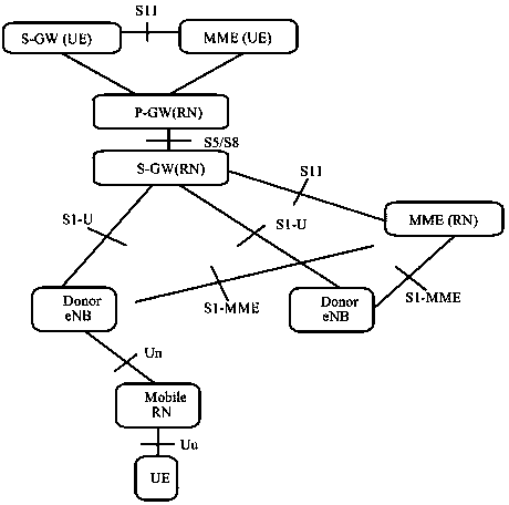
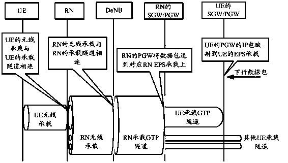
[0010] RN can select a closer P-GW (RN) / S-GW (RN) for RN according to the geographical location of the selected DeNB at startup; as RN moves, its serving DeNB leaves the initial location due to RN handover. The selected P-GW (RN) / S-GW (RN) may be farther and farther away; at this time, the transmission delay of the data packet between the P-GW (RN) / S-GW (RN) and the serving DeNB of the RN will increase It is getting bigger and bigger, resulting in lower user experience; and the transmission of large amounts of data over long distances will also consume the backhaul link resources between P-GW (RN) / S-GW (RN) and DeNB

Method used


Image

  • Method and equipment for transmitting data
  • Method and equipment for transmitting data
  • Method and equipment for transmitting data

Examples


Embodiment 1

[0080] Embodiment 1 of the present invention provides a data transmission method, so as to optimize the route of user plane data in the scenario of using mobile RN; Image 6 As shown, the method includes the following steps:

[0081] In step 601, the RN (mobile RN) obtains the transport layer care-of address assigned to itself by the target DeNB.

[0082]Method 1. Before the RN accesses the target DeNB, the RN obtains the transport layer care-of address from the handover command; Figure 7 As shown, it is a schematic diagram of the RN obtaining the transport layer care-of address from the handover command, and the process includes the following steps:

[0083] Step 701, the source DeNB sends a handover request to the target DeNB, the handover request carries an RN indication, and the RN indication is used to indicate that the handover node is an RN; in addition, the handover request may also carry an RN Context (context): such as RN's Capability information, configuration in...

Embodiment 2

[0126] Based on the same inventive concept as the above method, an embodiment of the present invention also provides a relay node RN, such as Figure 10 As shown, the relay node RN includes:

[0127] Obtaining module 11, configured to obtain the transport layer care-of address assigned to RN by the target donor base station DeNB; sending module 12, configured to notify the serving gateway S-GW corresponding to the user equipment UE of the transport layer care-of address, and the S - the GW uses the transport layer care-of address to send the data to be sent to the RN to the target DeNB.

[0128] The obtaining module 11 is specifically configured to obtain the transport layer care-of address by receiving a handover command from the source DeNB before accessing the target DeNB; wherein, the handover command carries the transport layer care-of address, and the The transport layer care-of address is notified by the target DeNB to the source DeNB through a handover request respons...

Embodiment 3

[0133] Based on the same inventive concept as the above method, the embodiment of the present invention also provides a serving gateway S-GW, the S-GW is the S-GW corresponding to the user equipment UE, such as Figure 11 As shown, the serving gateway S-GW includes:

[0134] Obtaining module 21, configured to obtain the transport layer care-of address assigned by the target donor base station DeNB to the relay node RN; sending module 22, configured to use the transport layer care-of address to send data that needs to be sent to the RN to the target DeNB.

[0135] The obtaining module 21 is specifically configured to obtain the transport layer care-of address by receiving a bearer modification request from a mobility management entity MME corresponding to the UE; wherein, the bearer modification request carries the transport layer care-of address, In addition, the transport layer care-of address is sent by the RN to the MME through a path switching request.

[0136] The sendi...


PUM


Abstract

The invention discloses a method and equipment for transmitting data. The method includes that relay nodes RN acquire transmission layer care-of addresses distributed by a target donor evolved node B DeNB for the relay nodes RN; the relay nodes RN inform serving gateways S-GW corresponding to user equipment UE of the transmission layer care-of addresses, and the serving gateways S-GW transmit the data which are required to be transmitted to the relay nodes RN to the target donor evolved node B DeNB by the aid of the transmission layer care-of addresses. The method and the equipment in an embodiment of the invention have the advantages that the relay nodes RN inform the serving gateways S-GW corresponding to the user equipment UE of the transmission layer care-of addresses which are distributed to the relay nodes RN by the target donor evolved node B DeNB, so that the serving gateways S-GW corresponding to the user equipment UE can directly transmit the data to the target donor evolved node B DeNB, the data can be prevented from being transmitted through P-GW (data packet networks gateway) (RN) / S-GW (RN) in data transmission procedures, the UE data packet transmission delay can be shortened, transmission load on a network can be reduced, return link resources between the P-GW (RN) / S-GW (RN) and the target donor evolved node B DeNB can be saved, and the user experience can be improved.

Description

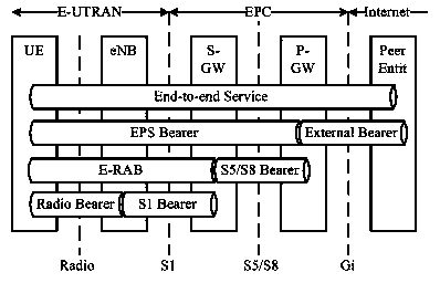
technical field [0001] The present invention relates to the field of communication technology, in particular to a data transmission method and equipment. Background technique [0002] Such as figure 1 As shown, it is a schematic diagram of EPS (Evolved Packet System, evolved packet system), and EPS bearer is established between UE (User Equipment, user equipment) and P-GW (Packet Data Networks Gateway, packet data gateway), using To transmit user plane data between the UE and the P-GW; the data packet sent by the UE is mapped to the corresponding EPS bearer, transmitted to the P-GW through the EPS bearer, and enters the external network in the form of an IP packet, and is routed to the communication peer; The data packet sent by the communication peer reaches the P-GW through the external network, and the P-GW maps the data packet to the corresponding EPS bearer, and sends it to the UE through the EPS bearer. [0003] It should be noted that the complete EPS bearer include...

Claims


Application Information

Patent Timeline
IPC IPC(8): H04W8/26H04W36/00H04W36/30
Inventor 鲍炜焦斌杨义
Owner DATANG MOBILE COMM EQUIP CO LTD
Learn More