Drive current generator, LED driver, illumination device, and display device

a technology of led driver and current generator, which is applied in the direction of static indicating devices, instruments, optics, etc., can solve the problems of undesirable efficiency reduction, and achieve the effect of minimizing efficiency reduction

Inactive Publication Date: 2007-11-08
ROHM CO LTD
View PDF10 Cites 18 Cited by
  • Summary
  • Abstract
  • Description
  • Claims
  • Application Information

AI Technical Summary

Benefits of technology

[0013] In view of the conventionally experienced problems described above, an object of the present invention is to provide drive current generators that can supply a desired driv

Problems solved by technology

This undesirably r

Method used


Image

  • Drive current generator, LED driver, illumination device, and display device
  • Drive current generator, LED driver, illumination device, and display device
  • Drive current generator, LED driver, illumination device, and display device

Examples


Embodiment Construction

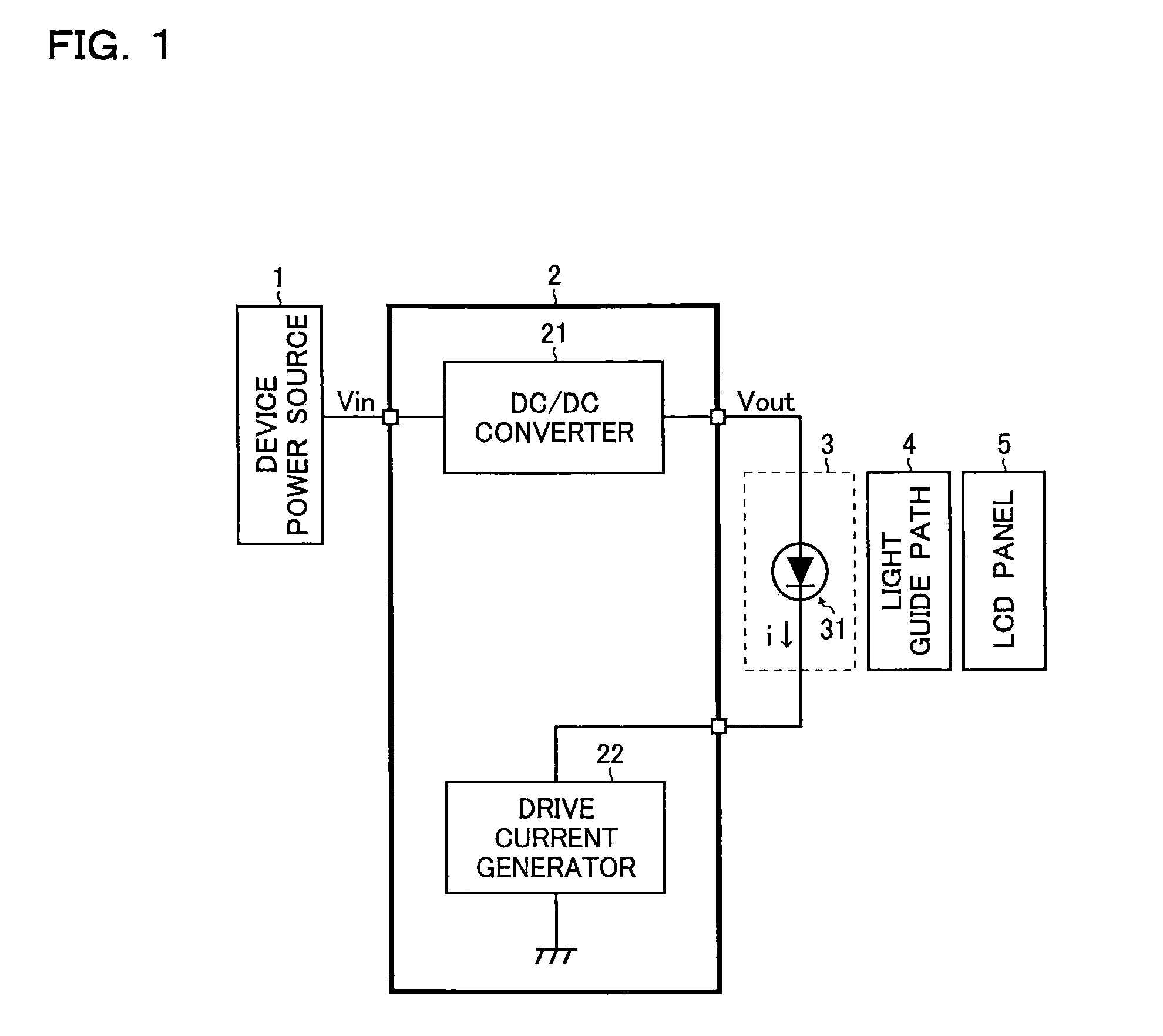
[0022]FIG. 1 is a block diagram showing an embodiment of a display device according to the invention. As shown in this figure, the display device of this embodiment is a transmissive liquid crystal display including a device power source 1, an LED driver IC 2, a light-emitting portion 3, a light guide path 4, and a liquid crystal display panel 5 (hereinafter “LCD (liquid crystal display) panel 5”).

[0023] The device power source 1 supplies electric power to the LED driver IC 2 and other parts of the display device; it may be an AC / DC converter that produces a DC (direct-current) voltage from a commercially distributed AC (alternating-current) voltage, or a battery such as a rechargeable battery.

[0024] Supplied with an input voltage Vin from the device power source 1, the LED driver IC 2 drives and controls a light-emitting diode (hereinafter “LED”) 31 that forms the light-emitting portion 3. The LED driver IC 2 includes: a DC / DC converter 21 that produces, from the input voltage Vi...


PUM


Abstract

A drive current generator that supplies a desired drive current to an LED has: a drive transistor that is connected in series between one end of the LED and a ground; a first current control portion that performs conductivity control of the drive transistor in such a way that a monitoring voltage commensurate with a current flowing through a reference resistor equals a predetermined reference voltage, and that produces an intermediate current that behaves in the same way as a drive current; a current mirror portion that produces a mirror current commensurate with the intermediate current at a given ratio, and that feeds the mirror current thus produced back to the reference resistor; and a second current control portion that keeps the ratio of the drive current to the intermediate current at a given value. With this configuration, it is possible to supply a desired drive current to the load while minimizing the reduction in efficiency.

Description

[0001] This application is based on Japanese Patent Application No. 2006-128938 filed on May 8, 2006, the contents of which are hereby incorporated by reference. BACKGROUND OF THE INVENTION [0002] 1. Field of the Invention [0003] The present invention relates to drive current generators that supply a desired drive current to a load, and to LED (light-emitting diode) drivers, illumination devices, and display devices incorporating such drive current generators. For example, the present invention relates to an LED backlight system for liquid crystal displays. [0004] 2. Description of Related Art [0005]FIGS. 6A and 6B are block diagrams each showing an example of a conventional LED driver. [0006] As shown in FIG. 6A, a conventional LED driver includes, as a means for generating a drive current i of a light-emitting diode LED, a drive transistor N0, a sense resistor Rs1, and an amplifier AMP. This conventional LED driver is so configured as to perform conductivity control of the drive t...

Claims


Application Information

Patent Timeline
IPC IPC(8): G09G3/36G02F1/13357H01L33/00H05B37/02
CPCG09G3/3406
Inventor NAKAO, SHIGEHARUOMIYA, YUJI
Owner ROHM CO LTD
Why Eureka
Try Eureka