
Bottle made of plastic material having a gripping portion

a plastic material and a gripping technology, applied in the direction of container/bottle construction, rigid containers, containers, etc., can solve the problems of large amount of plastic material being used, the resistance of vertical loads, and the inability to increase the volume of the bottle excessively

Inactive Publication Date: 2007-11-08
DES EAUX MINERALES DEVIAN
View PDF17 Cites 64 Cited by
  • Summary
  • Abstract
  • Description
  • Claims
  • Application Information

AI Technical Summary

Benefits of technology

[0013]It is therefore an object of the present invention to meet these requirements while providing a gripping portion which is comfortable for the majority of users.
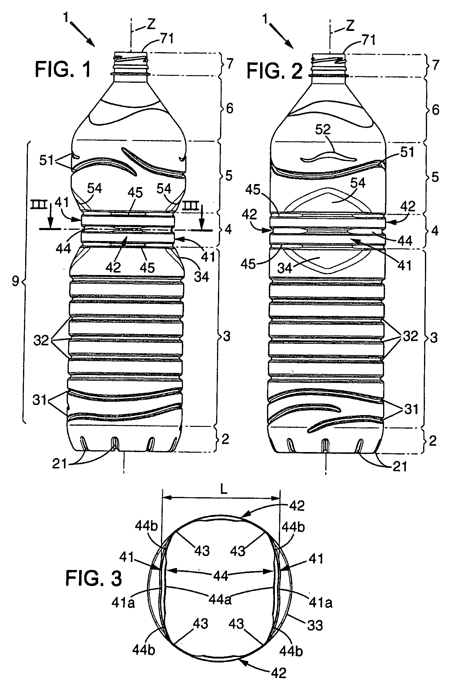
[0015]By virtue of these arrangements, a gripping portion of particularly simple shape, which is therefore sparing in terms of plastic material, is obtained, with gripping panels which are flat but resistant to pressure by virtue of the reinforcing relief. Moreover, the vertical stresses are of course transmitted by the connecting portions but above all by the corners connecting the connecting panels which, because of their radius of curvature which is much smaller than that of the panels of the gripping zone, behave structurally like girders. Applying these arrangements has made it possible to produce 1.5 l and 2 l bottles which satisfy the tests of transport strength and user convenience while having a lower weight than bottles of the same capacity which are currently sold and are less easy to take in the hand.
[0019]the flute has a depth at the corners which is appreciably smaller than the depth in the central zone of the gripping panels, which makes it possible to favor the transmission of vertical stresses in the zone of the corners whereas, in the central zone of the gripping panels, the resistance to radial deformation is favored;
[0022]the gripping panels have in their central zone a slight recessed depression, which makes it possible to distribute the pressure exerted by a thumb, for example, and thus to avoid folding of the flute by localized concentration of force;

Problems solved by technology

Gripping bottles for pouring their contents poses problems for some users when the capacity reaches 1.5 l, and for the majority of them as of a capacity of 2 l, on account of the transverse dimensions of the body of the bottle, given that the height of the bottle cannot be increased excessively for fear of causing awkward tipping as a result of displacement of the liquid during pouring.
However, such a solution poses problems of resistance to the vertical load to which the bottle is subjected during transport.
Nevertheless, in order to obtain a handle shape which is sufficiently small for the hand of the majority of users, the hollows have to be deep, which results in a large amount of plastic material being used and may pose problems of resistance to large increases in internal pressure which arise during transport.
During transport, under the effect of the load of stacked bottles and other factors, the bottles inevitably undergo increases in internal pressure.
If a portion of the wall of the body is deformed excessively, the volume of the bottle increases, the internal pressure decreases and the bottle is crushed vertically, which may result in a stack of pallets of bottles tipping.

Method used


Image

  • Bottle made of plastic material having a gripping portion
  • Bottle made of plastic material having a gripping portion
  • Bottle made of plastic material having a gripping portion

Examples


first embodiment

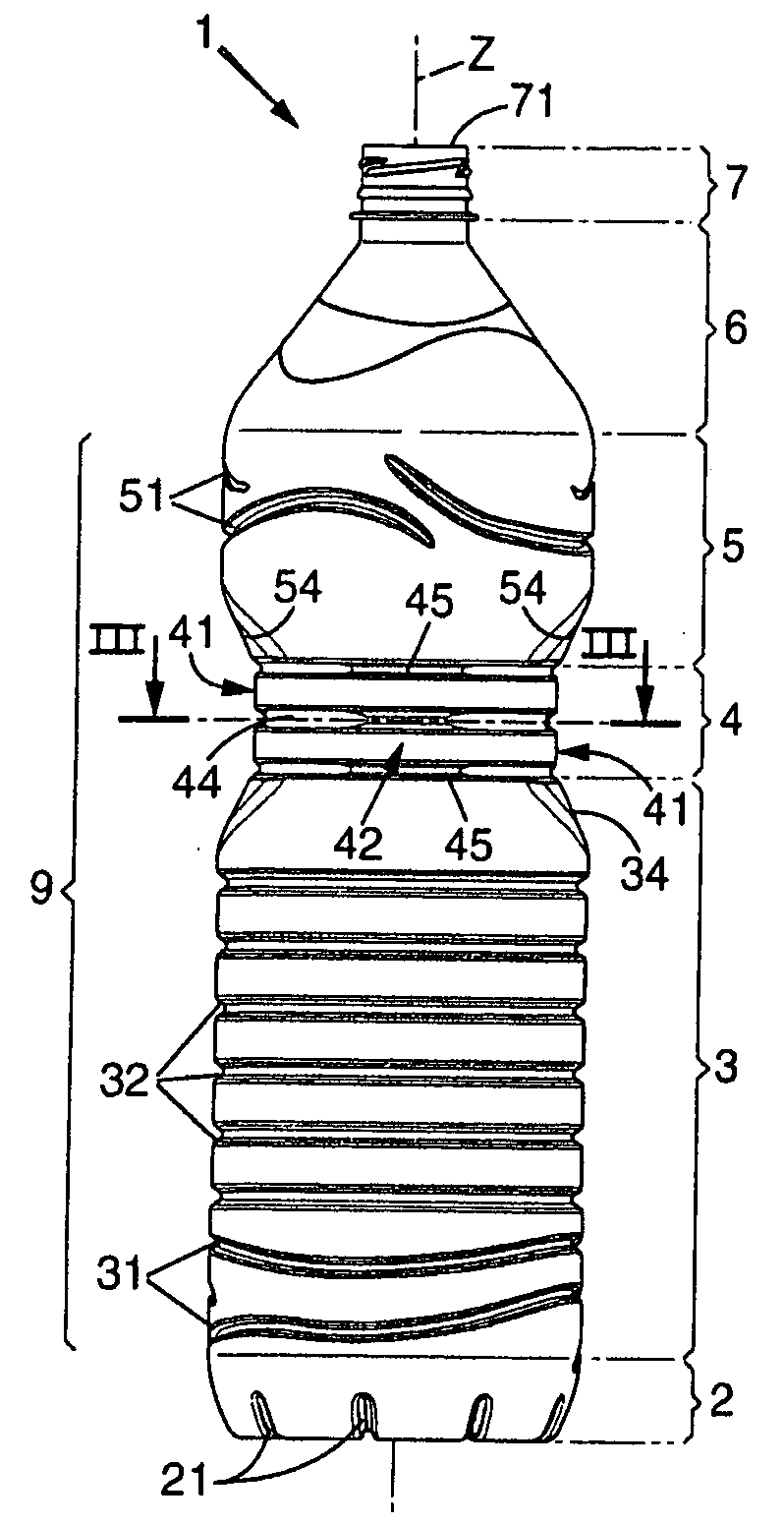
[0058]The gripping panels 41 have a length, measured in a transverse plane, which is greater than their height. The gripping panels therefore have a transversely oriented elongate rectangular shape. In this first embodiment, the gripping portion extends over a height of roughly 3 cm, which proves to be sufficient for good taking in the hand and for locating a number of reinforcing flutes, possibly with sections of different shape. For these reasons, however, it is preferable if the gripping panels 41 have at least in a central zone a height greater than 2 cm. However, the gripping panels are not to have a maximum height greater than 5 cm because, with such a large dimension, it is more difficult to meet the requirements of rigidity of these panels and reduced weight of the bottle.

[0059]The gripping panels 41 are connected at their lower longitudinal end to the lower portion 3 by inclined surfaces 34, here of an on the whole triangular shape owing to the circular section of the body ...

second embodiment

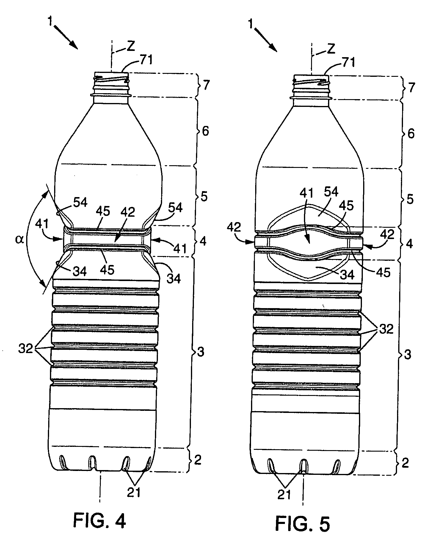
[0063]the gripping panels applied here to a 1.5 l capacity bottle 1 is shown in FIGS. 4 and 5. The majority of the component elements of this bottle are similar in all respects to those of the embodiment shown in FIGS. 1 to 3 and will not be described in detail again. The profile of the cross section of the upper and lower portions 3, 5 (not shown for this embodiment) is likewise circular but of a smaller diameter of roughly 88 mm, which makes it possible to space the gripping panels at a slightly smaller distance L, namely roughly 72 mm, which likewise represents around 82% of the major dimension.

[0064]Here, the gripping panels 41 comprise only two reinforcing flutes 45 arranged at the longitudinal ends of these panels. These upper and lower flutes each constitute an undulation, directed upward and downward respectively, in the central zone of the gripping panels 41. The maximum height of these panels is therefore, as in the preceding embodiment, of the order of 2 cm in order to pr...


PUM


Abstract

A bottle made of plastic material having a body extending along a central axis which comprises:a lower portion having a cross section with an essentially constant profile, followed bya gripping portion, and ending inan upper portion having a section with an essentially constant profile arranged in alignment with the profile of the section of the lower portion.The gripping portion comprises two globally plane gripping panels arranged parallel to one another and in relation to the central axis at a distance which is adapted for a hand taking. These panels have at least one reinforcing relief which extends in a transverse plane and are interconnected by connecting panels extending in continuation of the lower and upper portions by means of rounded corners located at the circumferential ends of the panels.

Description

[0001]The present invention relates to a bottle made of plastic material having a gripping zone intended in particular but not exclusively for containing a large quantity of drink.[0002]More specifically, the invention relates to a bottle having a bottom from which a body extends longitudinally along a central axis to a neck which ends in a ring forming a pouring opening and is adapted to receive a closing element, said body comprising from the bottom to the neck:[0003]a lower portion having a cross section with an essentially constant profile, followed by[0004]a gripping portion, and ending in[0005]an upper portion having a section with an essentially constant profile arranged in alignment with the profile of the section of the lower portion.BACKGROUND OF THE INVENTION[0006]Bottles of this type have to satisfy various constraints associated with their transport and the pouring convenience for the user while having to be as light as possible in order to reduce costs associated with ...

Claims


Application Information

Patent Timeline
Patent Type & Authority Applications(United States)
IPC IPC(8): B65D90/02
CPCB65D1/0223B65D2501/0036B65D23/102
Inventor COLLOUD, ALAIN
Owner DES EAUX MINERALES DEVIAN
Learn More