
Portioning unit

a technology of proportioning unit and dividing plate, which is applied in the field of proportioning unit to achieve the effect of convenient cleaning, maintenance and repair

Inactive Publication Date: 2007-10-25
KB SYST
View PDF3 Cites 5 Cited by
  • Summary
  • Abstract
  • Description
  • Claims
  • Application Information

AI Technical Summary

Benefits of technology

[0019]Therefore, it is an objective of the present invention to create a portioning unit, and in particular a partitioning drum for same, which facilitates cleaning, maintenance, and repair and which in particular allows for a respective retrofitting of the portioning unit.
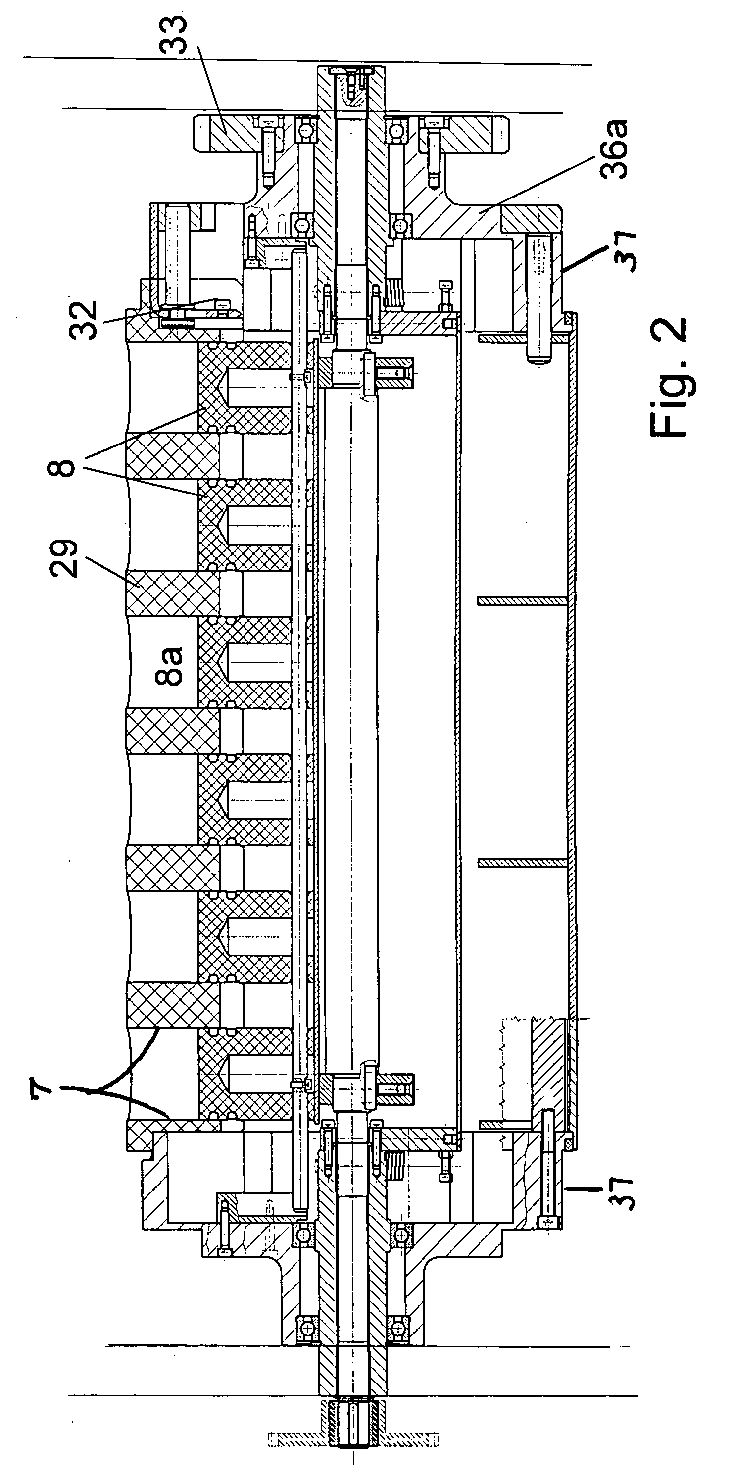
[0025]By having not just the portioning pistons but the entire cylinder bar made of plastic material, preferable POM (Polyoxymethylen), and not requiring any embedded metal components, such cylinder bars can be manufactured relatively simply and inexpensively through machining plastic blocks. After removing the cylinder bars from the partitioning drum, cleaning of the bars, especially by mechanical means, is considerably simplified, as when mounted in the partitioning drum.
[0027]All components of the partitioning drum next to the portioning cylinder which axially extend into its radial area, thus, also the frontal head pieces and e.g. their drive gears for the partitioning drum, are further removed in an axial direction from the cylinder bar in operating position than the axial distance of offset, in order to assure assembly and disassembly without problems.
[0030]The guiding plate can also be divided into individual segments in axial direction which, however, only increases manufacturing costs while keeping the profile constant in axial direction. A sequence of guide curves with different shapes in axial direction for the individual partitioning pistons or the axial sections of the partitioning drum is possible, e.g. in order to produce dough billets of different sizes with one partitioning drum; however, it increases manufacturing costs for the guide curve and for the support cam supporting the guide curve from its radially anterior, radially inner surface.

Problems solved by technology

When removing such cylinder bars in axial direction it has proven to be disadvantageous because sufficient space has to be provided next to the partitioning drum and, furthermore, because the frontal head pieces of the partitioning drum must allow such extraction which would require substantial additional work, especially when retrofitting a portioning unit with such a partitioning drum.

Method used


Image

  • Portioning unit
  • Portioning unit
  • Portioning unit

Examples


Embodiment Construction

[0045]FIG. 1 shows a side view of the portioning unit of the present invention wherein the relevant components, such as a radial pusher 4, a partitioning drum 6, a kneading drum 120, and associated conveyor belts, e.g. a kneading belt 140, and respective guide pulleys of these belts, can be dimensioned perpendicular to the drawing plane of FIG. 1 in any way depending on the capacity requirements of the unit.

[0046]In the following, an overall description of the kneading sequence is provided with reference to FIG. 1.

[0047]Finished dough is filled into a dough container 11 where it passes through an open upper filler port 4′ of a radial pusher 4.

[0048]In a partitioning drum 6, on its surface, working orifices are disposed, distributed along different generatrices, as can be seen in FIG. 3. The volume of these orifices is variable through partitioning pistons 8 moving therein.

[0049]Partitioning drum 6 rotates permanently, being charged through a pushing motion of radial pusher 4 every t...


PUM

PropertyMeasurementUnit
axial displacementaaaaaaaaaa
longitudinal displacementaaaaaaaaaa
diameteraaaaaaaaaa

Abstract

In a dough billet kneading machine, in order to be able to remove and clean the partitioning cylinders, which are radially moveable in the partitioning drum, they are grouped in a linear manner into cylinder bars along a generatrix, and these cylinder bars can not be removed in axial direction, but in radial direction, greatly reducing the space required for maintenance operations.

Description

CROSS-REFERENCE TO RELATED APPLICATIONS[0001]This application claims priority to German Patent Application No. 10 2006 018 626.5-23 filed 21 Apr. 2006.STATEMENT REGARDING FEDERALLY SPONSORED RESEARCH OR DEVELOPMENT[0002]Not ApplicableTHE NAMES OF THE PARTIES TO A JOINT RESEARCH AGREEMENT[0003]Not ApplicableINCORPORATION-BY-REFERENCE OF MATERIAL SUBMITTED ON A COMPACT DISC[0004]Not ApplicableBACKGROUND OF THE INVENTION[0005](1) Field of the Invention[0006]This invention relates to portioning units for doughy materials, especially dough in bakeries, as employed in the partitioning of a large charge of dough into defined small portions or dough billets.[0007](2) Background Art[0008]Portioning units are used in industrial baking plants for the partitioning of finished dough according to a preset weight into individual dough pieces (herein referred to as dough billets) and are used to additionally form the dough billets into a flat, round shape, similar to that of a wheel of cheese. Howe...

Claims


Application Information

Patent Timeline
Patent Type & Authority Applications(United States)
IPC IPC(8): B28B3/12B28B5/00
CPCA21C5/04
Inventor BRUNNER, KARL HEINZSCHUTZ, OTTO
Owner KB SYST
Learn More