
Voltage level shifter apparatus

Inactive Publication Date: 2007-10-25
FARADAY TECH CORP
View PDF8 Cites 35 Cited by
  • Summary
  • Abstract
  • Description
  • Claims
  • Application Information

AI Technical Summary

Benefits of technology

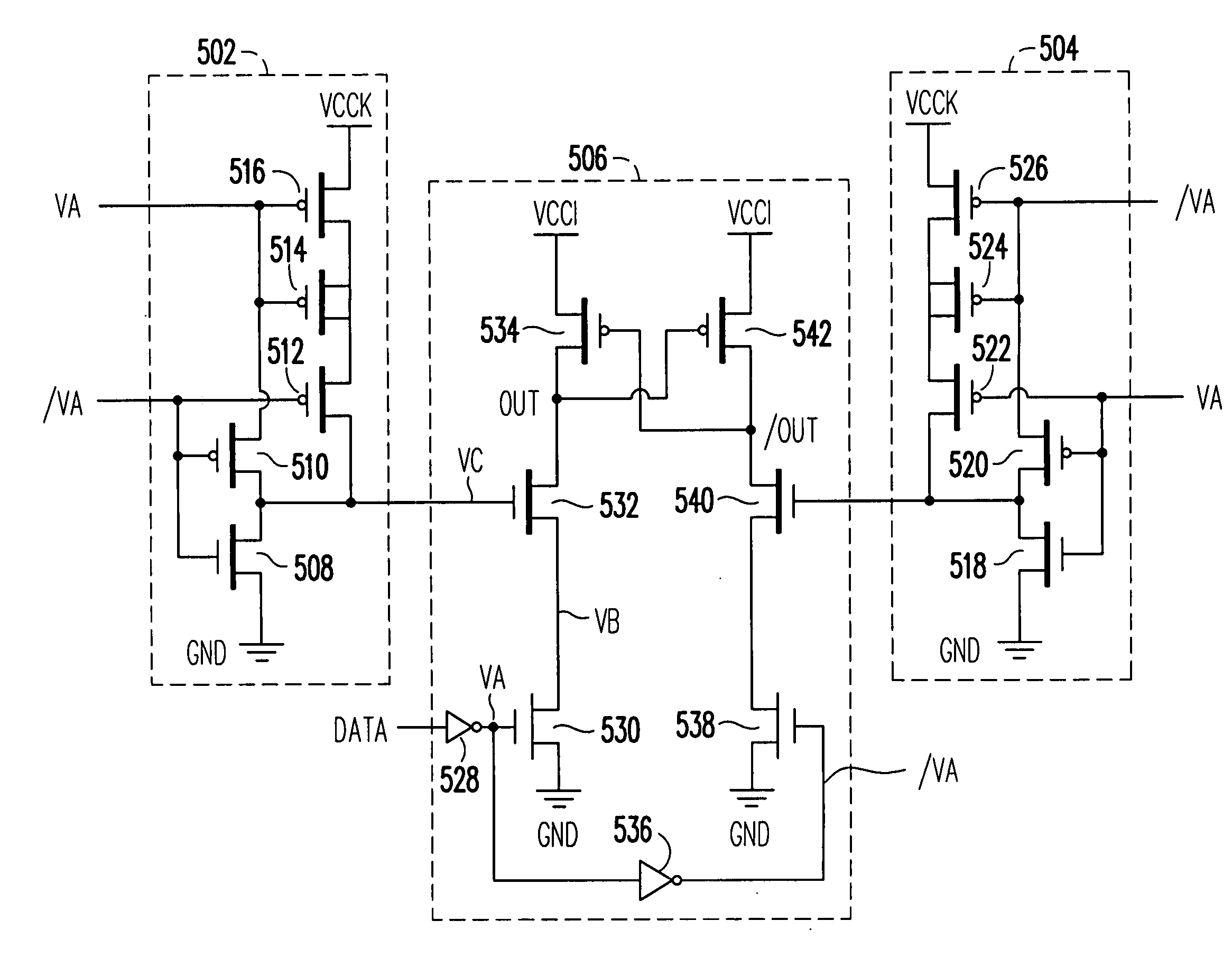
[0012] An object of the present invention is to provide a dynamic-bias voltage level shifter apparatus without the extra current leakage from the bias circuit.
[0014] In the present invention, the desired level of the bias signal in the voltage level shifter apparatus is dynamically determined according to the input data signal, thus the extra current leakage from the bias generators can be eliminated and power consumption is thereby saved. Additionally, in the present invention, no OPAMP and feedback path are needed, thus no additional leakage caused by the OPAMP will exist, and the performance of the voltage level shifter apparatus will not be influenced due to the waiting for a feedback.

Problems solved by technology

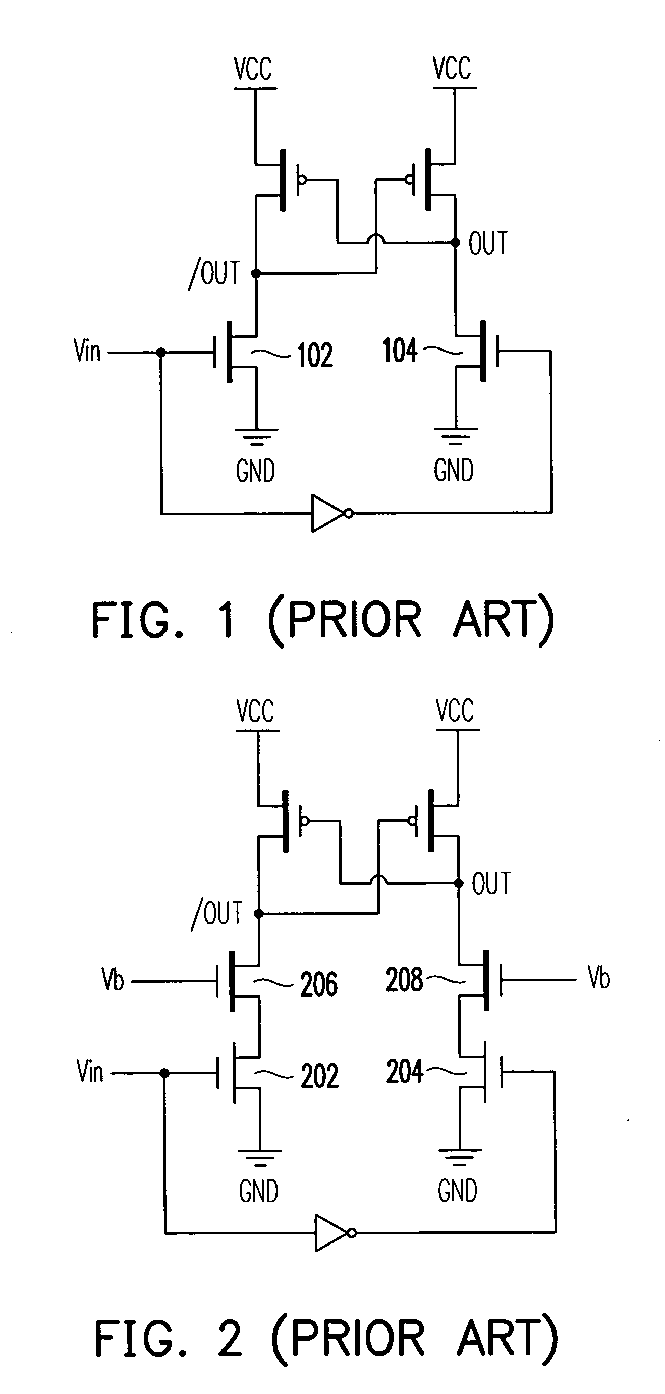
However, since the input signal Vin is often provided from the inside of the integrated circuit chip and the level thereof becomes lower with the progress of integrated circuit processes.
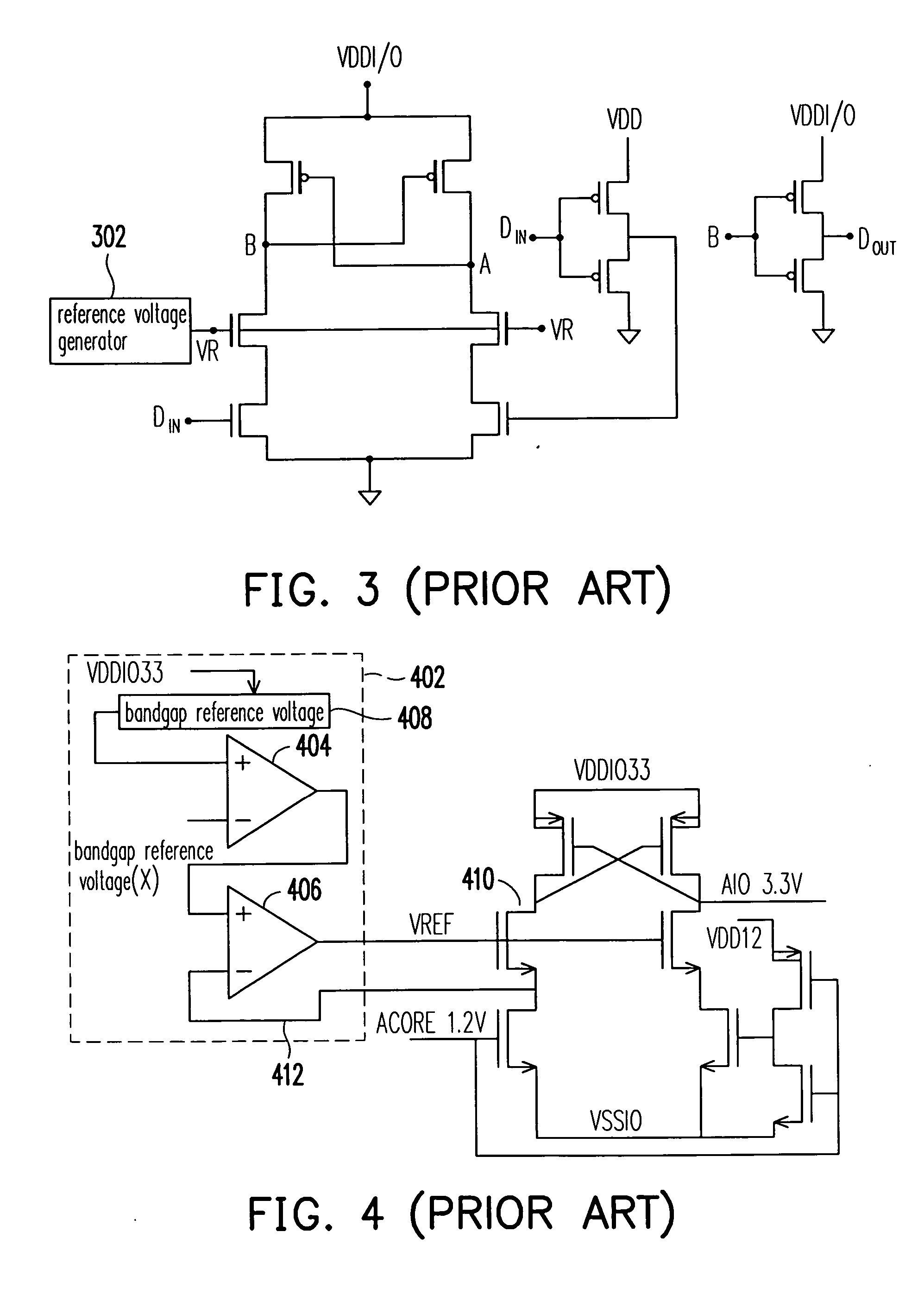
And thus, the output of the voltage level shift circuit becomes very unstable and therefore such a method is not suitable.
Since the fixed bias signal maintains the transistor in a biased state, a certain degree of stand-by leakage will be generated, which consumes more electric energy.
Moreover, since a bias signal also needs to be additionally provided for the OPAMPs 404 and 406 themselves for an operation, a leakage phenomenon will occur.
Furthermore, such a bias signal is still a fixed-type one and therefore still generates stand-by leakage such that more electric energy will be consumed.
Thus, all technical products which apply a voltage level shift circuit are negatively influenced.

Method used


Image

  • Voltage level shifter apparatus
  • Voltage level shifter apparatus
  • Voltage level shifter apparatus

Examples


Embodiment Construction

[0023]FIG. 5 shows a voltage level shifter apparatus according to a preferred embodiment of the present invention. FIG. 6 is a diagram of signal measurement in the voltage level shifter apparatus of FIG. 5. Referring to FIGS. 5 and 6 at the same time, the voltage level shifter apparatus includes a first dynamic-bias generator 502, a second dynamic-bias generator 504, and a level supply circuit 506. The first dynamic-bias generator 502 and the second dynamic-bias generator 504 respectively generate a first bias signal and a second bias signal using an inversion input data signal VA in addition to an in-phase signal / VA of the input data signal DATA. With the inverter 528 in the level supply circuit 506, VA is generated from the input signal DATA as its inversion signal. In addition, / VA is an inversion signal of VA through the inverter 536 of the level supply circuit 506. Furthermore, / VA is an in-phase signal of DATA.

[0024] Continue to refer to FIG. 5, the first dynamic-bias genera...


PUM


Abstract

A voltage level shifter apparatus is provided. The voltage level shifter apparatus includes a first dynamic-bias generator, a second dynamic-bias generator, and a level supply circuit. The first dynamic-bias generator dynamically outputs a first bias signal, wherein the level of the first bias signal is determined in accordance with the received input data signal. The second dynamic-bias generator outputs a second bias signal, wherein the level of the second bias signal is determined in accordance with the received input data signal. Besides receiving the input data signal, the level supply circuit is further coupled to the first dynamic-bias generator and the second dynamic-bias generator for receiving the first bias signal and the second bias signal, and generating the output data signal in accordance with the input data signal, the first bias signal, and the second bias signal.

Description

BACKGROUND OF THE INVENTION [0001] 1. Field of Invention [0002] The present invention relates to a voltage level shifter apparatus. More particularly, the present invention relates to a voltage level shifter apparatus using dynamic-bias. [0003] 2. Description of Related Art [0004] With the development of technology, and following the trend that current development of technical products is pursuing slightness, thinness, shortness, and small volume while providing increasingly stronger functionality, the power used by inner circuits of technical products has been reduced accordingly; furthermore, the quantity and variety of adopted circuits and integrated circuit chips have become greater than ever, so ultra low voltage level in circuits or integrated circuit chips often need to be shifted to higher voltage level for the applications of the advanced technologies. A voltage level shift circuit is an apparatus used for providing the necessary voltage level shift. [0005]FIG. 1 shows a co...

Claims


Application Information

Patent Timeline
IPC IPC(8): H03L5/00
CPCH03K3/356104
Inventor CHEN, CHUEN-SHIU
Owner FARADAY TECH CORP
Learn More