
Pneumatic Tire

a pneumatic tire and tire technology, applied in the field of pneumatic tires, can solve the problems of road noise generated not only at 160 hz to 200 hz, but at any frequency band, so as to reduce the resonant vibration of the suspension, reduce the ideal footprint of the tire, and reduce the effect of car interior nois

Inactive Publication Date: 2007-10-25
BRIDGESTONE CORP
View PDF1 Cites 7 Cited by
  • Summary
  • Abstract
  • Description
  • Claims
  • Application Information

AI Technical Summary

Benefits of technology

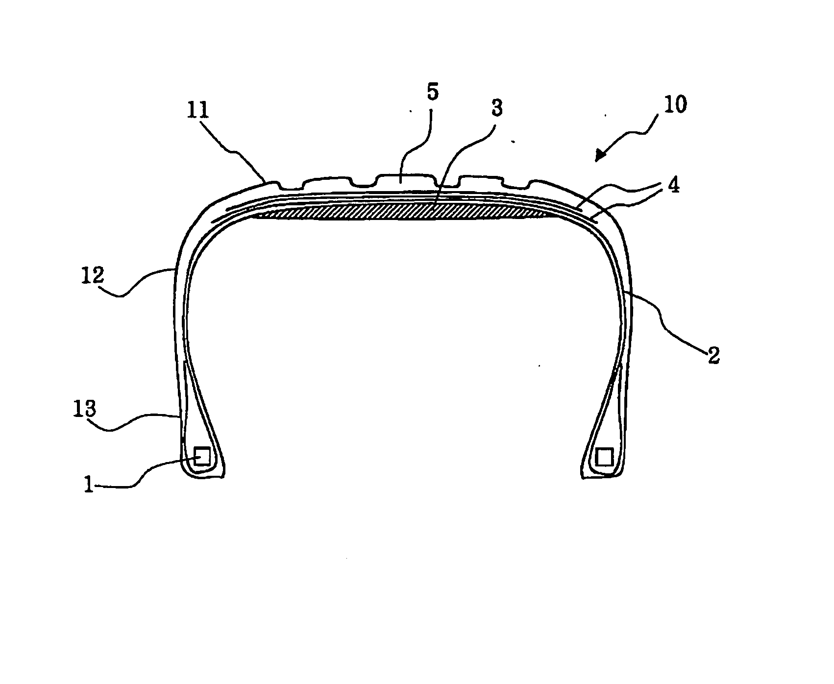
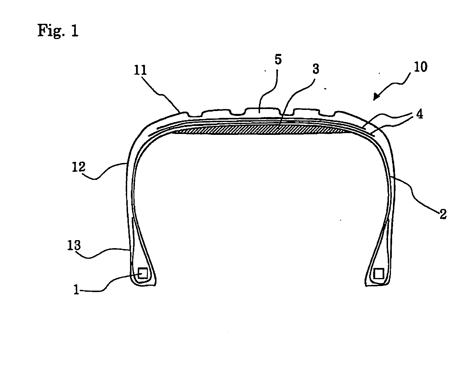
[0022] As described above, Patent Document 3 describes a pneumatic tire including a predetermined rubber film inside the tire. This rubber film must have an elongation at break of at least 900% to prevent air leakage from a flat tire. However, a rubber layer according to the present invention aims to increase the weight, as described below, and therefore does not need such a high elongation at break. For example, the elongation at break of a rubber layer according to the present invention is supposed to be about 700% or less. Patent Document 4 describes a pneumatic tire including a predetermined insulation rubber disposed between a carcass ply and an inner liner rubber. This insulation rubber has a thickness approaching substantially zero in the center area of a tread. Hence, Patent Document 4 is different in technical idea from the present invention, in which it is important to place a rubber layer in the vicinity of the center area of a tread.

Problems solved by technology

However, noise actually exists at frequencies of 160 Hz to 200 Hz, which is generated from a tire and a wheel.
However, the road noise is generated not only at 160 Hz, but also at any frequency band.

Method used


Image

  • Pneumatic Tire
  • Pneumatic Tire
  • Pneumatic Tire

Examples


examples

[0056] The specific effects of the present invention are described below using a PSR185 / 60R14 pneumatic tire illustrated in FIGS. 4 to 6.

example 1

[0058] A tire 10B illustrated in FIG. 5(a) was produced by attaching a rubber layer 3B having a thickness of 3 mm and a width of 120 mm to an inner surface of an inner carcass ply 2 corresponding to a tread 11 of the tire 10A illustrated in FIG. 4(a). The rubber layer 3B was formed of a rubber of the same type as a coating rubber of a carcass ply and had a modulus of elasticity at 100% elongation of 2.0 MPa.

example 2

[0059] A tire 10C illustrated in FIG. 6(a) was produced by attaching a rubber layer 3C to the carcass 2 of the tread 11, as in the tire 10B. The rubber layer 3C had a modulus of elasticity at 100% elongation of 2.0 MPa. The rubber layer 3C had a width of 140 mm and different thicknesses at the center and the shoulders (both ends). The thickness of a portion having a width of 60 mm around the center was 4 mm and the thickness in the other portions was 2 mm. The weights of the tire 10B and the tire 10C were larger by about 1 kg than that of the tire 10A.

(Measurement of Car Interior Noise)

[0060] The car interior noise of the sample tires 10A to 10C were measured while a vehicle is moving. The vehicle was a common passenger car of 1800 cc displacement equipped with a strut type front suspension. The car interior noise was measured when the vehicle equipped with each sample tires run at a speed of 60 km / h on a common-road.

[0061] A peak frequency appeared at about 170 Hz. When the sou...


PUM


Abstract

The present invention provides a pneumatic tire that has a tire structure modified to reduce the road noise and thereby reduce the car interior noise and that exhibits improved high-speed drivability and improved high-speed durability. The pneumatic tire includes a circular tread, a pair of sidewalls and beads on both sides of the tread, and a carcass extending between bead cores within the pair of beads. A rubber layer having a modulus of elasticity at 100% elongation in the range of 1.0 MPa to 30 MPa and a thickness in the range of 2.0 mm to 5.0 mm is placed inside the carcass and at at least part of a portion around the center of the tread.

Description

TECHNICAL FIELD [0001] The present invention relates to a pneumatic tire (hereinafter referred to simply as “tire”), and more particularly to a pneumatic tire that generates a low car interior noise and that exhibits excellent high-speed drivability and excellent high-speed durability. BACKGROUND ART [0002] In general, a pneumatic tire vibrates in various modes when a vehicle is running. In particular, a vibration in the vicinity of 160 Hz to 200 Hz (road noise) sounds as a grating noise for a driver. These vibrations result from a combination of various elements, such as the automobile structure, the suspension structure, the wheel structure, and the tire structure. For example, a vibration at 160 Hz to 200 Hz is known to increase or decrease in a manner that depends on the type of vehicle. However, noise actually exists at frequencies of 160 Hz to 200 Hz, which is generated from a tire and a wheel. [0003] A recent study has reported that a car interior noise around 160 Hz results ...

Claims


Application Information

Patent Timeline
Patent Type & Authority Applications(United States)
IPC IPC(8): B60C9/02B60C5/00B60C9/08B60C19/00
CPCB60C11/0332Y10T152/10855B60C19/002
Inventor ISHIYAMA, MAKOTOMOTOORI, OSAMU
Owner BRIDGESTONE CORP
Learn More