Exposure Apparatus, Exposure Method, Method for Producing Device, and Optical Part
a technology of exposure apparatus and exposure light beam, which is applied in the direction of photomechanical apparatus, printing, instruments, etc., can solve the problems of insufficient margin, difficult to match the substrate surface with respect to the image plane of the projection optical system, and restricted optical part material, which is usable for the exposure light beam with the increasingly shortened wavelength, so as to achieve satisfactory exposure accuracy and satisfactory measurement accuracy
- Summary
- Abstract
- Description
- Claims
- Application Information
AI Technical Summary
Benefits of technology
Problems solved by technology
Method used
Image
Examples
first embodiment
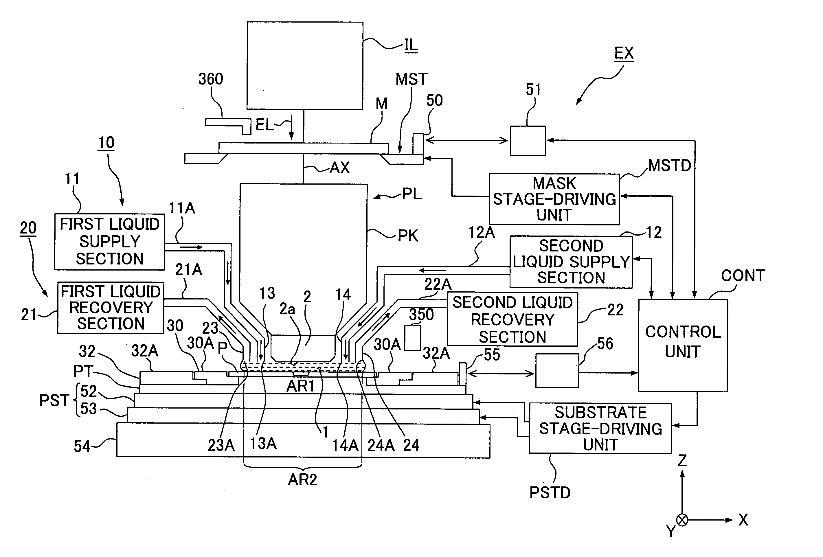
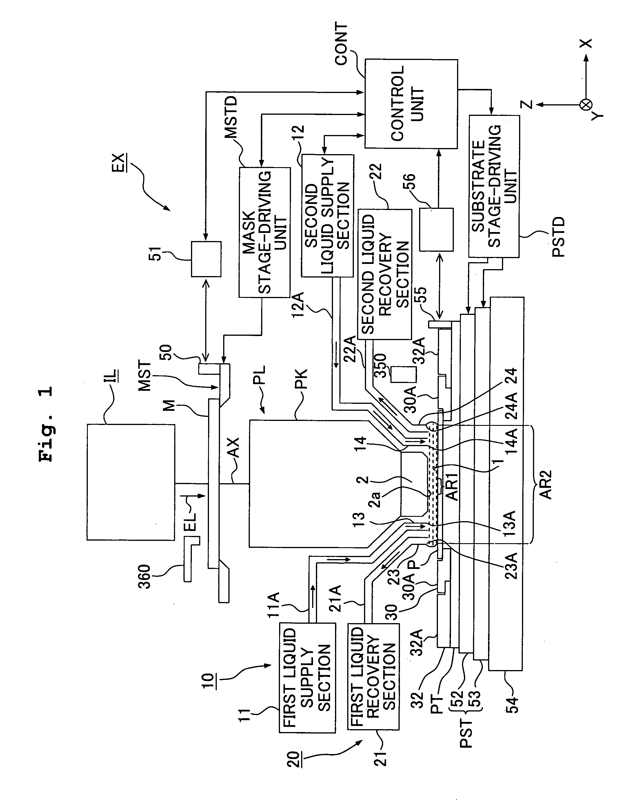
[0052]FIG. 1 shows a schematic arrangement illustrating an embodiment of the exposure apparatus of the present invention. With reference to FIG. 1, an exposure apparatus EX includes a mask stage MST which supports a mask M, a substrate stage PST which supports a substrate P by the aid of a substrate table PT, an illumination optical system IL which illuminates, with an exposure light beam EL, the mask M supported by the mask stage MST, a projection optical system PL which performs projection exposure for the substrate P supported by the substrate stage PST with an image of a pattern of the mask M illuminated with the exposure light beam EL, and a control unit CONT which integrally controls the overall operation of the exposure apparatus EX.
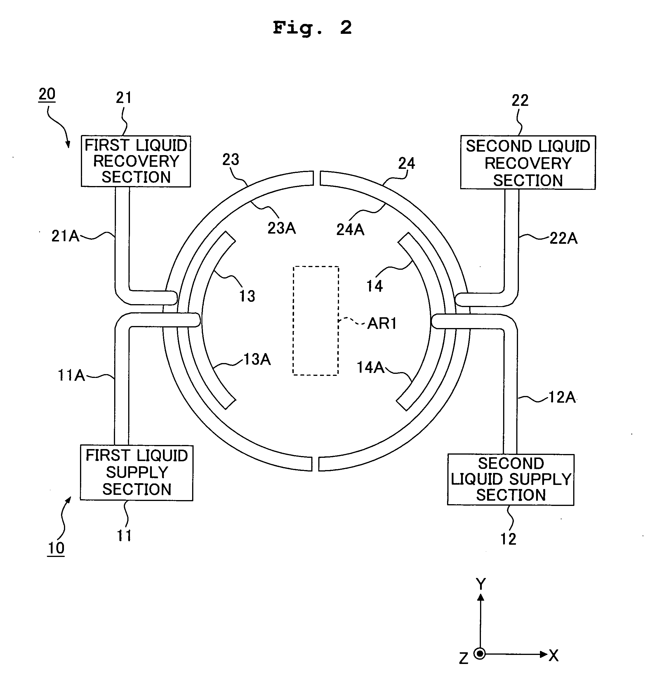
[0053] The liquid immersion method is applied to the exposure apparatus EX of the embodiment of the present invention in order that the exposure wavelength is substantially shortened to improve the resolution and the depth of focus is substantial...
second embodiment
[0136] Next, another embodiment of the present invention will be explained. In the following description, parts or components, which are the same as or equivalent to those of the embodiment described above, are designated by the same reference numerals, any explanation of which will be simplified or omitted.
[0137]FIG. 11 shows a substrate holder PH which is attached / detached with respect to the substrate table PT (substrate stage PST). FIG. 11(a) shows a side sectional view, and FIG. 11(b) shows a plan view as viewed from an upper position, illustrating the substrate table PT after the substrate holder PH is detached.
[0138] As shown in FIG. 11, the substrate table PT includes, on an upper surface thereof (holding surface for the substrate holder PH), a recess 157 to which the substrate holder PH is capable of being fitted, a plurality of vacuum suction holes 158 which are provided in the recess 157 and which attract and hold the substrate holder PH arranged in the recess 157, and ...
third embodiment
[0151] The foregoing embodiments have been explained such that the member (plate member 30, second plate member 32, substrate holder PH), which has the flat surface 30A around the substrate P, is exchanged depending on the deterioration of the liquid repellence thereof. However, it is desirable that any member other than the plate member 30, the second plate member 32, and the substrate holder PH provided on the substrate table PT has its liquid-repellent surface. It is appropriate that such a member is exchangeable depending on the deterioration of the liquid repellence thereof. In particular, it is desirable that the member, which makes contact with the liquid 1, has the liquid-repellent surface. It is appropriate that such a member is exchangeable depending on the deterioration of the liquid repellence thereof. Specifically, the constitutive members of the reference member 300 and the constitutive members of the optical sensors 400, 500, which are used while forming the liquid im...
PUM
| Property | Measurement | Unit |
|---|---|---|
| contact angle | aaaaa | aaaaa |
| contact angle | aaaaa | aaaaa |
| refractive index | aaaaa | aaaaa |
Abstract
Description
Claims
Application Information
 - R&D
- Intellectual Property
- Life Sciences
- Materials
- Tech Scout
- Unparalleled Data Quality
- Higher Quality Content
- 60% Fewer Hallucinations
Browse by: Latest US Patents, China's latest patents, Technical Efficacy Thesaurus, Application Domain, Technology Topic, Popular Technical Reports.
© 2025 PatSnap. All rights reserved.Legal|Privacy policy|Modern Slavery Act Transparency Statement|Sitemap|About US| Contact US: help@patsnap.com


