
Optical fiber sensor

a technology of optical fiber and sensor output, applied in the direction of force measurement, force measurement, optical property variation measurement, etc., can solve the problems of inability to keep the phase difference between the reference light and the signal light within this narrow range, inability to eliminate, and inaccuracy, etc., to reduce the system manufacturing cost, reduce the inaccuracy, and reduce the measurement error small

Active Publication Date: 2016-03-01
HAKUSAN CORP
View PDF8 Cites 0 Cited by
  • Summary
  • Abstract
  • Description
  • Claims
  • Application Information

AI Technical Summary

Benefits of technology

The present invention provides a method to measure the phase of light using a laser and optical fibers. The method is able to measure the phase of signal light and reference light to very small changes, such as drifts in the laser level or changes in the optical fiber loss. The method uses a calibration process to remove inaccuracy caused by these changes and ensures accurate measurement. The resulting measurement is highly accurate and stable, even in extreme circumstances, which reduces the need for precise control of phase between the signal and reference light. The method also extends the measurement range and dynamic range by using a multiple wavelengths and increasing the measurement period. Overall, the method reduces system manufacturing costs and allows for the use of more affordable components.

Problems solved by technology

In the conventional homodyne interferometer system, a sensor output signal is affected by fluctuation of a laser signal generator output level in accordance with temperature drift, which results in variation in an optical fiber transmission path and residual errors in the output value of the sensor output signal because the output value is calculated according to the condition that the reference light and the signal light intensities are constant.
Although the conventional homodyne interferometer system is able to detect the phase difference of a half of light wavelength between the reference light and the signal light, it is almost impossible to keep the phase difference between the reference light and the signal light within this narrow range because the components of the conventional homodyne interferometer system do not have excellent dimension accuracy in order to keep the phase difference into the narrow range.
Moreover, it is impossible to eliminate, in the conventional homodyne interferometer system, the optical path fluctuation by the influence of temperature variation in the surrounding environmental.

Method used


Image

  • Optical fiber sensor
  • Optical fiber sensor
  • Optical fiber sensor

Examples


Embodiment Construction

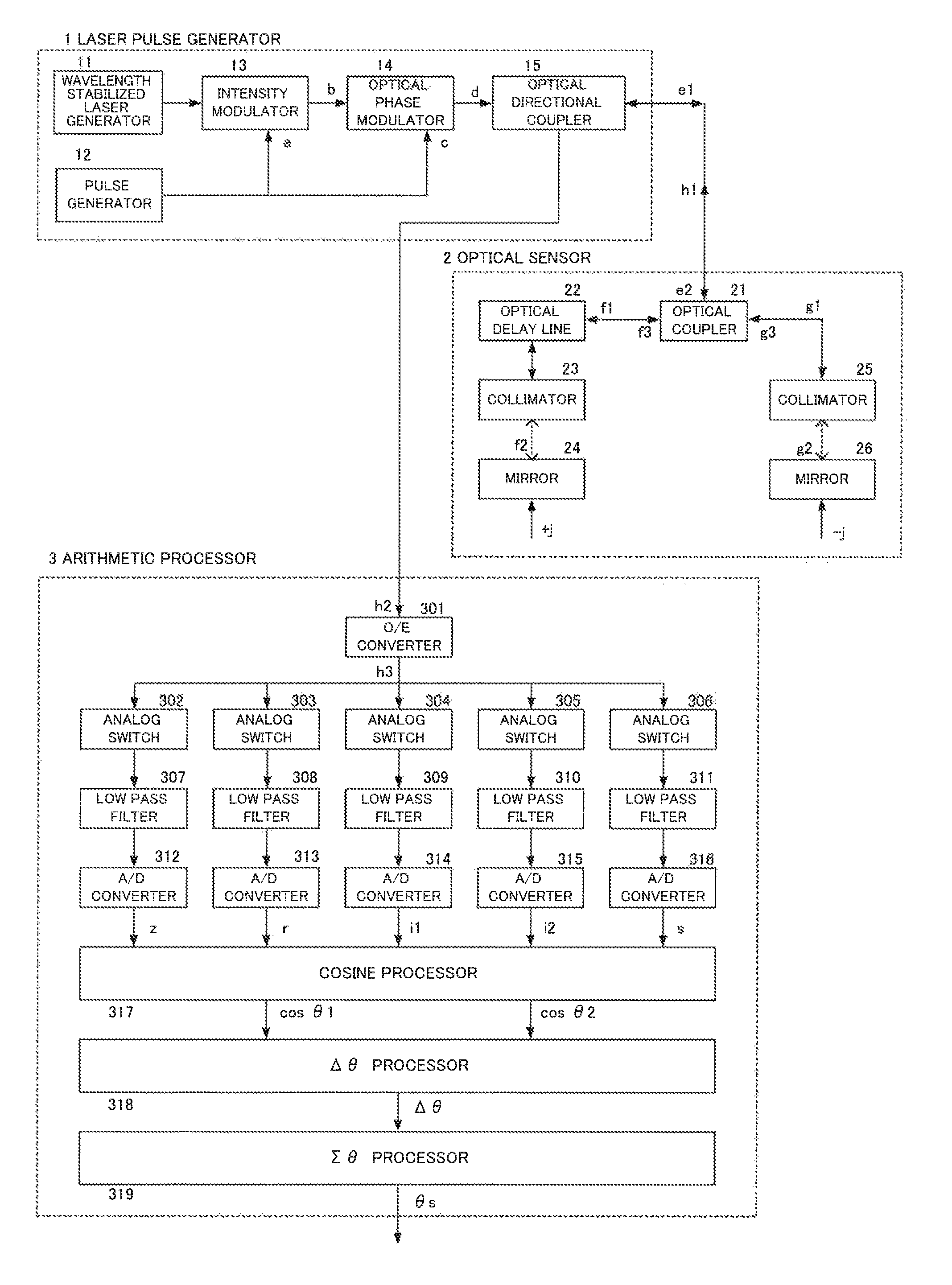
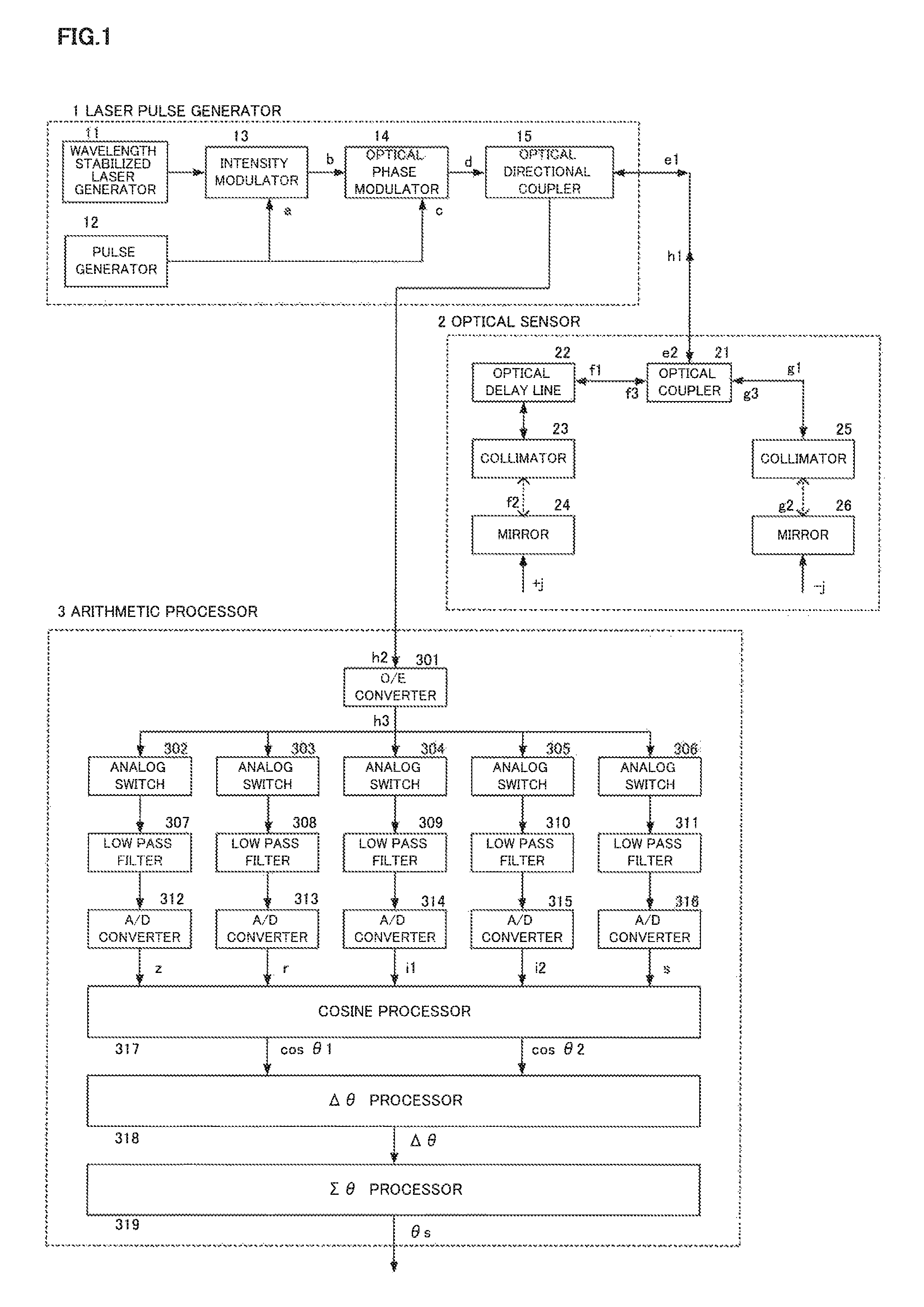
[0022]FIG. 1 is the example of the optical fiber sensor of the present invention, where a laser pulse generator 1, an optical sensor 2, and an arithmetic processor 3 are illustrated.

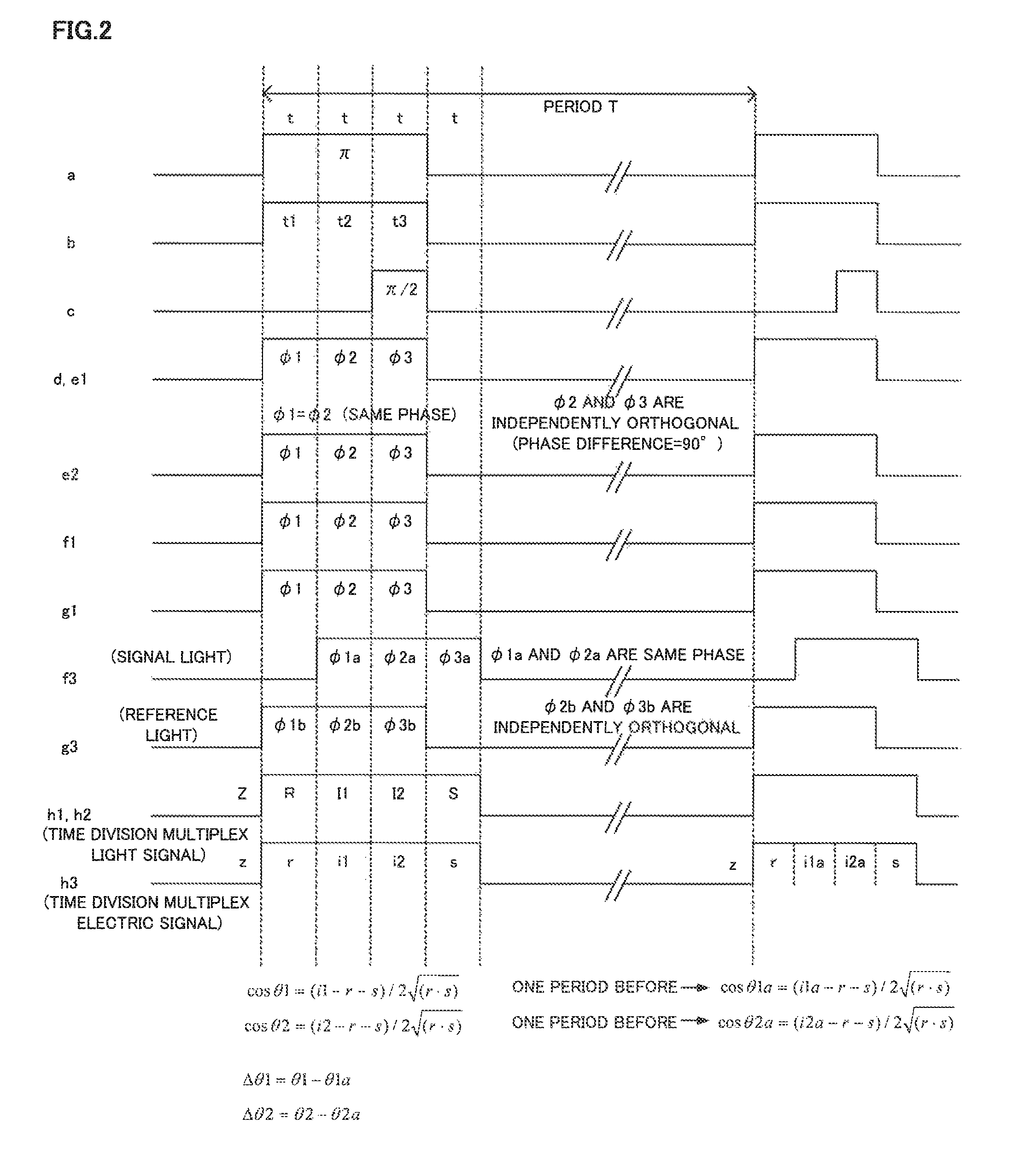
[0023]First, a laser pulse of 3t width in every T period is generated in the laser pulse generator 1, with which the light phase of front 2t portion is set to 0 degree (°) and last It portion 90 degree (°) in each other. The laser pulse is divided into two (2) by the optical coupler and one of which is applied to an optical sensor 2 through a t / 2 optical delay line. The other half of laser pulse is applied to the other input of the optical sensor 2. Both laser pulse phases are shifted in proportion to the external force applied to the optical sensor 2.

[0024]The reflected laser pulses, one through t / 2 optical delay line and the other directly, are combined by the optical coupler and the overall optical circuit forms a Michelson interferometer. The interferometer output laser pulse, i.e., the output optica...


PUM

PropertyMeasurementUnit
angleaaaaaaaaaa
pulse lengthaaaaaaaaaa
phaseaaaaaaaaaa

Abstract

An input of an optical interferometer is a periodical optical pulse. A phase of a first half and a latter half of a reference pulse is a 90 degree (independently orthogonal) phase difference. Two interferometric outputs i1 and i2, where the phase difference is 90 degrees from each other, are obtained by interference of the reference pulse and the signal pulse. θ is calculated by referring the amplitude of reference pulse and the signal pulse to remove the light intensity fluctuations. Two values of cos θ1 and cos θ2 are calculated and positions are determined on the cosine curve by obtaining θ1 and θ2 values. Δθ1 and Δθ2, which are the phase increment or decrement of both θ1 and θ2 in a T period, are summed and becomes the sensor output signal that removes the measurement range limitation of ±90 degrees (a half wavelength of light) of the light phase.

Description

TECHNICAL FIELD[0001]The present invention relates to an optical fiber sensor utilizing a distinctive character that a phase of an optical signal passing through an optical path is changed by an external force.BACKGROUND ART[0002]In a conventional homodyne interferometer system, if a phase difference between a reference light (R) and a signal light (S) is represented as θ, an interferometer output (I) is represented by the following formula:I=R+S+2√{square root over ( )}(R·S)cos θ(I, R and S are the laser power values.)θ=arccosine((I−R−S) / 2√{square root over ( )}(R·S))[0003]In the conventional homodyne interferometer system, a sensor output signal is affected by fluctuation of a laser signal generator output level in accordance with temperature drift, which results in variation in an optical fiber transmission path and residual errors in the output value of the sensor output signal because the output value is calculated according to the condition that the reference light and the sig...

Claims


Application Information

Patent Timeline
Patent Type & Authority Patents(United States)
IPC IPC(8): G01B9/02G01H9/00G01L1/24G01D5/353
CPCG01H9/004G01L1/242G01B9/02023G01D5/35335
Inventor TSUKADA, KAZUMASA
Owner HAKUSAN CORP
Learn More