Single fiber bidirectional optical module and single fiber bidirectional optical transmission and receiver device

a single fiber bidirectional optical module and bidirectional optical transmission technology, applied in the field of single fiber bidirectional optical modules and single fiber bidirectional optical transmission and receiver devices, can solve the problem that the module does not always include a single receiver, and achieve the effect of reducing electrical crosstalk

Active Publication Date: 2007-10-11
SUMITOMO ELECTRIC IND LTD
View PDF2 Cites 15 Cited by
  • Summary
  • Abstract
  • Description
  • Claims
  • Application Information

AI Technical Summary

Benefits of technology

[0014] According to the present invention, a chassis is connected to a receiver ground RG to reduce electrical crosstalk between a laser diode (LD) and a photodiode (PD), i.e., mixing of the driving current of the LD in the current of a light receiving element. Pins of the LD are floated from the metal chassis so that the chassis does not act as an antenna.
[0015] Further, according to the present invention, an insulative pipe formed of an insulative material such as zirconia insulates the chassis from a receptacle. Therefore, the adverse effect caused by the LD on an electrical element included in a frame can be eliminated.
[0022] The receptacle 4 is insulated by the insulative pipe 8 from the chassis 2 including the transmitter 5 and the receivers 6 and 7. The insulative pipe 8 insulates the frame 9 and the receptacle 4 from the chassis 2. The frame 9 and the receptacle 4 are connected to the frame ground FG. This configuration has the effect of preventing the LD from acting as an antenna to generate strong electromagnetic waves, preventing the crosstalk between the LD and the PD, and cutting off the electrical element of the frame 9 from the noise caused by the LD.
[0024] Any of lead pins 55, 56, 57, and 58 is not connected to and is insulated from the chassis 2. The lead pins 55, 56, 57, and 58 are connected to the anode of the LD, the cathode of the LD, the anode of the MPD, and the cathode of the MPD, respectively. The cathode and the anode of the LD are not connected to the chassis 2. A case for storing the LD is connected to the chassis 2. Thus, even if the LD package has a case pin, the case pin is not connected to the LD. Since the LD and the chassis 2 are insulated from each other, it is possible to prevent the chassis 2 from acting as an antenna to radiate the driving current of the LD and diffusing noise to the surroundings.
[0028]FIG. 4 similarly illustrates a configuration example of the LD+PD-type optical module of the present invention. The present example is approximately the same as the example illustrated in FIG. 3 but slightly different in the lead pins of the LD and the MPD. In FIG. 4, the anode of the LD and the cathode of the MPD are joined together and connected to a lead pin 59. This configuration can be formed in such a circuit connecting the power supply potential of the transmitter to the anode of the LD and the cathode of the MPD. With this configuration, one of the lead pins of the transmitter can be saved.
[0033] In the optical module according to the present invention, the chassis 2 including the LD and the PD is connected to the receiver ground RG, and the lead pins of the LD are insulated from the chassis 2. Further, the receptacle 4 is insulated from the chassis 2 by the insulative pipe 8, and the frame 9 including the receptacle 4 is connected to the frame ground FG. Since the pins of the LD are not connected to the chassis 2, the chassis 2 is prevented from acting as an antenna to generate the electromagnetic waves of the LD driving signal. Accordingly, the noise of the LD is not radiated to the surroundings. Further, since the receiver 6 is covered by the metal chassis 2 and connected to the receiver ground RG, the outer noise does not enter the receiver 6. Furthermore, since the LD and the chassis 2 are insulated from each other, the electromagnetic and electrical crosstalk between the LD and the PD can be suppressed. As described above, according to the present invention, it is possible to prevent the LD from externally diffusing the noise, to reduce the crosstalk between the LD and the PD, and to suppress the mixing of the outer noise into the receiver.

Problems solved by technology

However, the optical module does not always include a single receiver, and may include two light receiving elements.

Method used


Image

  • Single fiber bidirectional optical module and single fiber bidirectional optical transmission and receiver device
  • Single fiber bidirectional optical module and single fiber bidirectional optical transmission and receiver device
  • Single fiber bidirectional optical module and single fiber bidirectional optical transmission and receiver device

Examples


Embodiment Construction

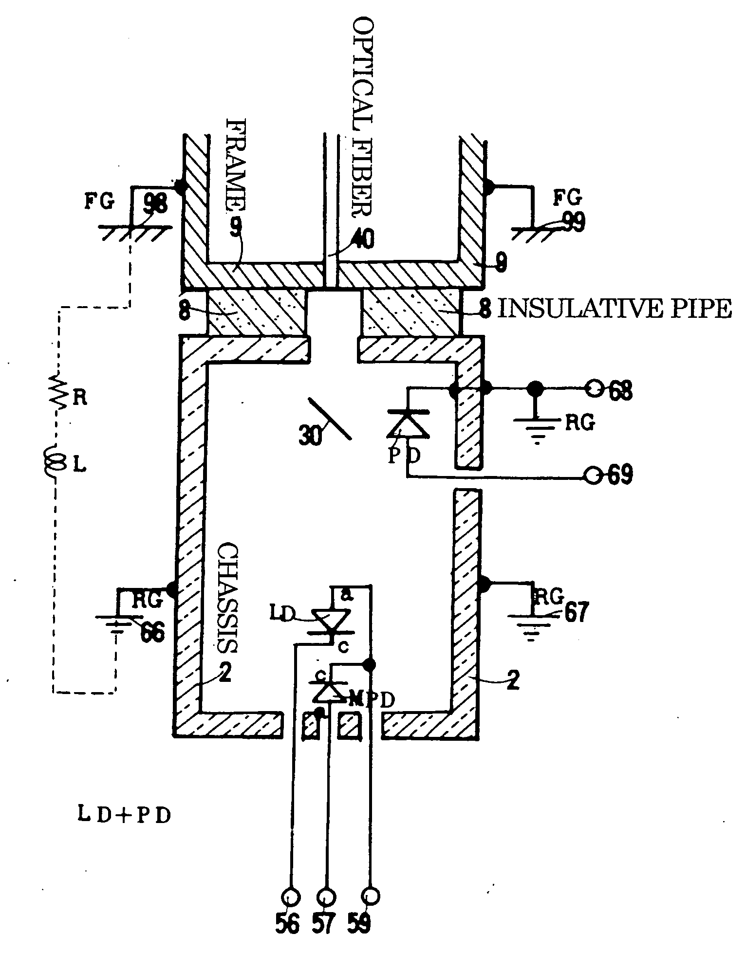
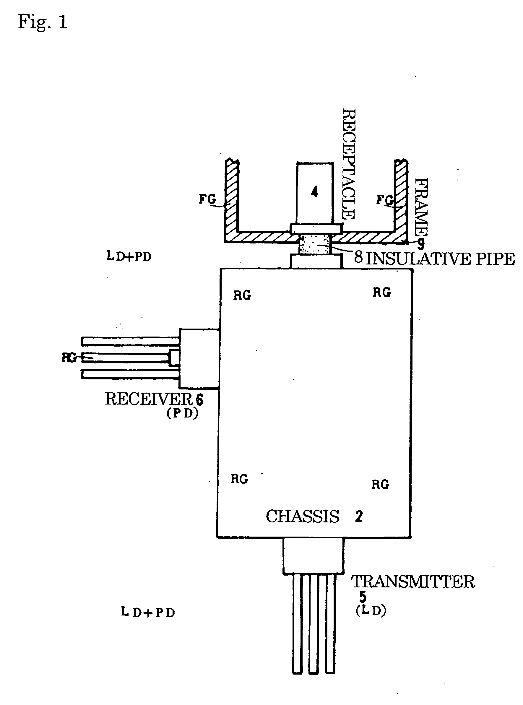
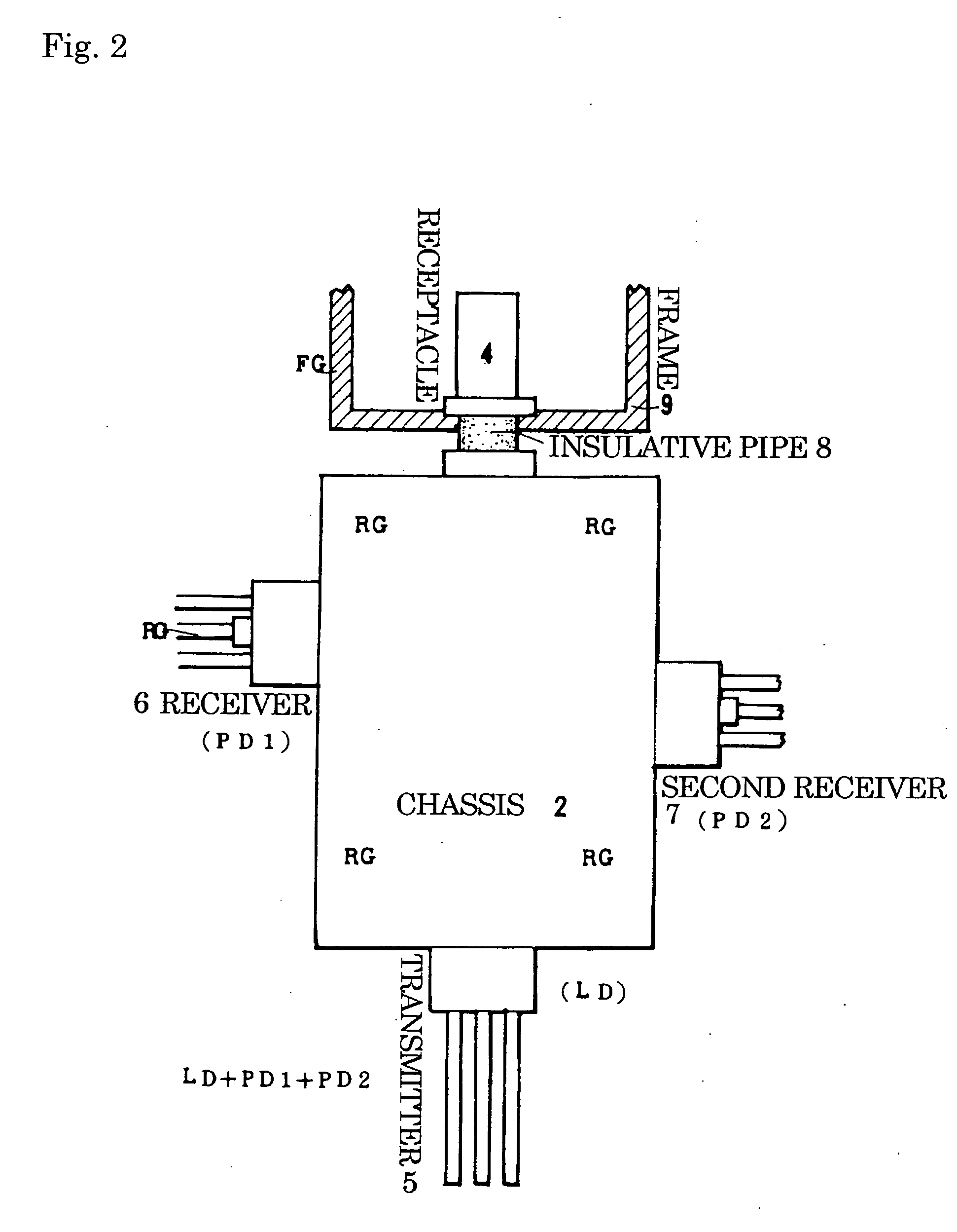
[0044] Embodiment 1: FIG. 7 is a front view of the exterior of a bidirectional optical module according to an embodiment of the present invention. FIG. 8 is a longitudinal sectional view of the optical module. In the optical module, a transmitter 5 including a laser diode (LD) and a monitor photodiode (MPD) is provided at a lower part of the optical module, and a receiver 6 including a photodiode (PD) is provided at the right side of the optical module. Further, a receptacle 4 is provided at an upper part of the optical module, and a wavelength selective filter 30 is provided between the receptacle 4 and the transmitter 5. The figures illustrate the state in which an optical fiber 40 is not inserted in the receptacle 4. To transmit an optical signal, a ferrule provided at the leading end of the optical fiber 40 is inserted in the receptacle 4 to optically couple the optical fiber 40 to the LD and the PD.

[0045] To electrically insulate the receptacle 4 from a metal chassis 2, a cyli...


PUM


Abstract

A metal chassis including a laser diode (LD) and a photodiode (PD) is held at a receiver ground RG, which is the potential of the anode or the cathode of the PD. Meanwhile, a receptacle for removing an optical fiber is held at a frame ground FG of a separate frame. Lead pins of the LD are insulated from the metal chassis. The receiver ground RG and the frame ground FG are insulated from each other by an insulative member. Since the receiver ground RG is insulated from the LD and the frame, a receiver is not easily affected by inner noise and outer noise. Accordingly, a bidirectional optical module having reduced influence of forward radiated noise, LD / PD crosstalk, and the outer noise is provided.

Description

BACKGROUND OF THE INVENTION [0001] 1. Field of the Invention [0002] The present invention relates to a single-fiber bidirectional optical module including a transmitter, a receiver, and a receptacle for bidirectionally transmitting a signal through a single optical fiber. In the bidirectional optical module, the present invention particularly has objects to suppress forward radiated noise, to reduce crosstalk between a laser diode (LD) and a photodiode (PD), and to reduce outer noise. [0003] 2. Description of the Background Art [0004] In optical communication for bidirectionally transmitting an optical signal by using a single optical fiber, an optical transmission and reception module is provided at opposite ends of the optical fiber. According to a conventional optical transmission and reception module, an optical fiber is drawn from an LD module which stores an LD in a metal package, and another optical fiber is drawn from a PD module which stores a PD in a metal package. Then, t...

Claims


Application Information

Patent Timeline
IPC IPC(8): G02B6/36
CPCG02B6/4246
Inventor OKADA, TAKESHI
Owner SUMITOMO ELECTRIC IND LTD
Why Eureka
Try Eureka