Optical module

a technology of optical modules and optical components, applied in the field of optical modules, can solve the problems of suppressing the crosstalk between the first wiring pattern and the technique of the first wiring pattern, and achieve the effects of reducing electrical crosstalk, high-quality transmission characteristics, and reducing malfunctions

Active Publication Date: 2018-02-13
LUMENTUM JAPAN INC
View PDF11 Cites 0 Cited by
  • Summary
  • Abstract
  • Description
  • Claims
  • Application Information

AI Technical Summary

Benefits of technology

[0018]It is an object of the invention to reduce electrical crosstalk, reduce malfunctions, and enable high-quality transmission characteristics.
[0019](1) An optical module according to an aspect of the invention includes: an optical sub-assembly for converting an optical signal and an electric signal at least from one to the other; and a flexible wiring board electrically connecting to the optical sub-assembly, wherein the optical sub-assembly includes an optical interface and an electrical interface provided on the sides opposite to each other, the electrical interface includes an insulating body and a plurality of electrodes, the insulating body including a plurality of front edge surfaces facing in a direction along a transmission direction of the optical signal at the optical interface and having different heights, the plurality of electrodes being provided on the insulating body so as to have a thickness or length from the plurality of front edge surfaces in a direction of the height, and the flexible wiring board includes a plurality of areas extending in directions along the plurality of front edge surfaces of the insulating body, and includes, in the plurality of areas, a plurality of pads electrically connected with the plurality of electrodes. According to the aspect of the invention, the heights of the plurality of front edge surfaces are different. Therefore, a connecting portion between the electrode and the pad on any of the front edge surfaces and a connecting portion between the electrode and the pad on the next front edge surface are distant from each other, so that crosstalk is reduced.

Problems solved by technology

In the optical module described above, the technique for suppressing the crosstalk between the first wiring pattern and the second wiring pattern is insufficient, and thus involves the problem of malfunction or the like of the optical module due to noise or the like.

Method used


Image

  • Optical module
  • Optical module
  • Optical module

Examples


first embodiment

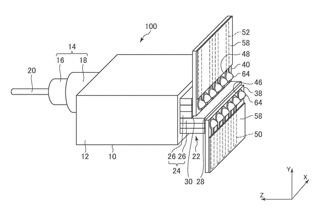
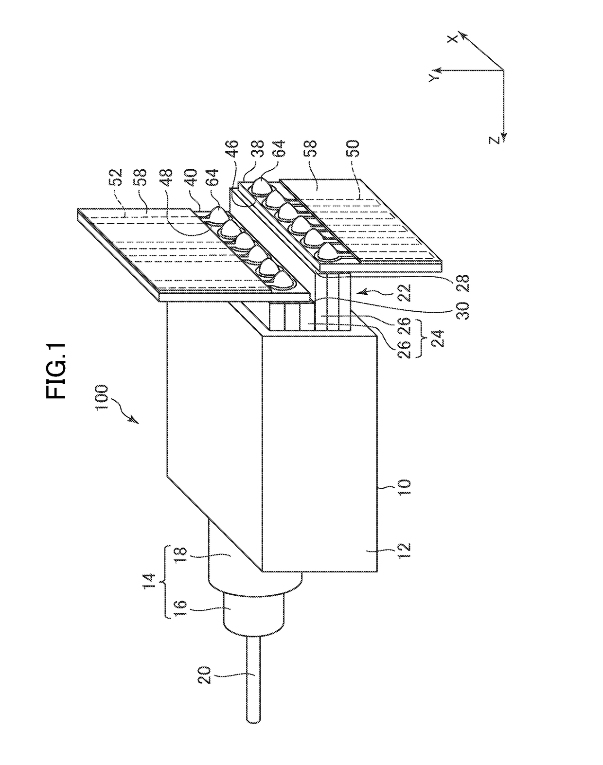
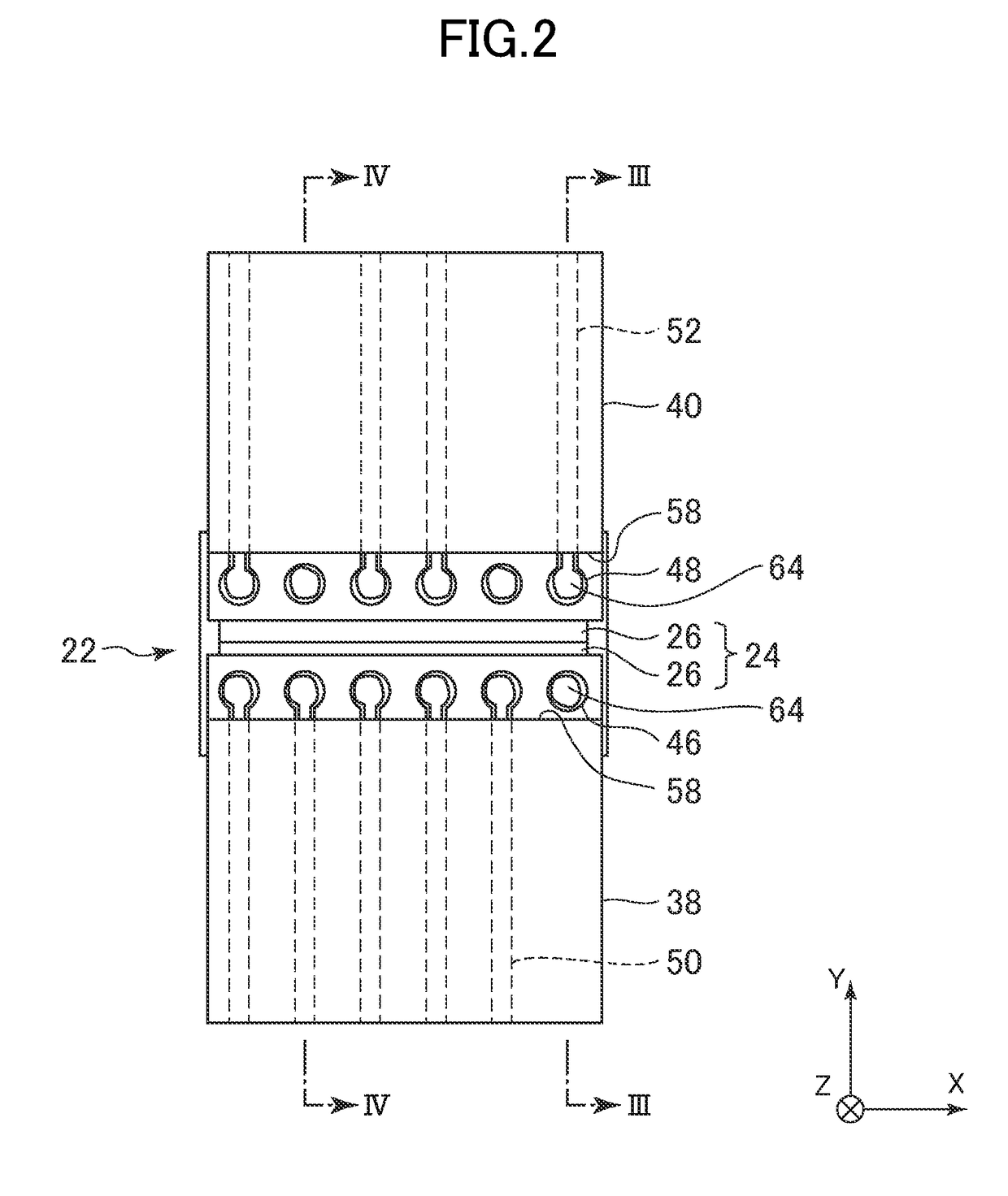
[0040]FIG. 1 is a perspective view for explaining an outline of an optical module of a first embodiment of the invention. The optical module 100 includes an optical sub-assembly 10 for converting an optical signal and an electric signal at least from one to the other. Examples of the optical sub-assembly 10 include: an optical transmission module (transmitter optical sub-assembly (TOSA)) that includes a light-emitting element such as a laser therein, coverts an electric signal to an optical signal, and transmits the optical signal; an optical reception module (receiver optical sub-assembly (ROSA)) that includes a light-receiving element represented by a photodiode therein, and converts a received optical signal to an electric signal; and a bidirectional optical sub-assembly (BOSA) having the functions of the TOSA and the ROSA. As described above, the optical sub-assembly 10 is configured to convert an electric signal and an optical signal at least from one to the other.

[0041]The opt...

second embodiment

[0060]FIG. 5 is a perspective view for explaining an outline of an optical module of a second embodiment of the invention. FIG. 6 is a cross-sectional view of the optical module taken along the line VI-VI shown in FIG. 5.

[0061]An insulating body 224 includes a first side surface 266 extending in the transmission direction of an optical signal and an electric signal to be adjacent to a first front edge surface 228. Each of a plurality of first electrodes 232 is a first lead pin provided on the first side surface 266. The first electrode 232 as the first lead pin penetrates each of a plurality of first pads 246 of a first flexible wiring board 238.

[0062]The insulating body 224 includes a second side surface 268 extending in the transmission direction of an optical signal and an electric signal to be adjacent to a second front edge surface 230. Each of a plurality of second electrodes 234 is a second lead pin provided on the second side surface 268. The second electrode 234 as the seco...

third embodiment

[0066]FIG. 7 is a perspective view for explaining an outline of an optical module of a third embodiment of the invention. FIG. 8 is a cross-sectional view of the optical module taken along the line VIII-VIII shown in FIG. 7.

[0067]Some of a plurality of first pads 346 are connected to first wiring patterns 350. At least one of the plurality of first pads 346 is connected to a first planar pattern 354. The first pad 346 connected to the first wiring pattern 350 and the first pad 346 connected to the first planar pattern 354 are next to each other in a staggered arrangement.

[0068]The content described in the second embodiment can be applied to the other structures of the embodiment. As a modified example, the staggered arrangement of a first flexible wiring board 338 may be applied to a second flexible wiring board 340. That is, a second pad connected to a second wiring pattern and a second pad connected to a second planar pattern may be arranged so as to be next to each other in a sta...


PUM


Abstract

An electrical interface includes an insulating body, first electrodes, and second electrodes. The insulating body includes a first front edge surface and a second front edge surface facing in a direction along a transmission direction of an optical signal at an optical interface and having different heights. The first electrode and the second electrode are provided on the insulating body so as to have a thickness from the first front edge surface and the second front edge surface in a direction of the height. A first flexible wiring board and a second flexible wiring board include a first area and a second area extending in directions along the first front edge surface and the second front edge surface, respectively, of the insulating body, and include, in the first area and the second area, first pads and second pads electrically connected with the first electrodes and the second electrodes.

Description

CROSS-REFERENCE TO RELATED APPLICATION[0001]The present application claims priority from Japanese application JP2015-060524 filed on Mar. 24, 2015, the content of which is hereby incorporated by reference into this application.BACKGROUND OF THE INVENTION[0002]1. Field of the Invention[0003]The present invention relates to an optical module.[0004]2. Description of the Related Art[0005]An optical reception module or optical transmission module used in the present market of optical communications has generally the form of a coaxial type package or box type package. In the package, a light-receiving element or / and a light-emitting element, and a modulating element and an amplifier IC or the like, if needed, are contained. Moreover, a lens, a fiber, and the like are accommodated in the package for inputting / outputting an optical signal from / to the outside. For example, in the optical reception module, the beam spot of an optical signal input through an optical fiber is narrowed by a lens...

Claims


Application Information

Patent Timeline
Patent Type & Authority Patents(United States)
IPC IPC(8): G02B6/36H01P1/00H01P5/00H05K3/36H05K1/11G02B6/42H04B10/00H05K1/14
CPCG02B6/4278G02B6/4281H05K1/118H05K3/363H05K1/115H05K2201/10303H05K1/147H05K1/148H05K3/366H05K2201/10121H05K1/117
Inventor BAN, TAKUMA
Owner LUMENTUM JAPAN INC
Why Eureka
Try Eureka