
LED lamp conducting structure with plate-type heat pipe

a technology of conducting structure and led lamp, which is applied in the direction of discharge tube main electrodes, semiconductor devices of light sources, lighting and heating apparatus, etc., can solve the problems of high cost, possible short circuit, and important heat dissipation issues, and achieve good thermal conductivity

Inactive Publication Date: 2007-10-11
PYROSWIFT HOLDING CO LIMITED
View PDF7 Cites 142 Cited by
  • Summary
  • Abstract
  • Description
  • Claims
  • Application Information

AI Technical Summary

Benefits of technology

[0012] Accordingly, the present invention provides an LED lamp conducting structure with plate-type heat pipe of mask shape. A support plate mounted with LEDs is fixed on a plate-type heat pipe and then is placed within a lampshade. The plate-type heat pipe is made of metal with good thermal conductivity and has a plurality of through holes defined on bottom thereof. The support plate includes a plurality of electrode holes corre

Problems solved by technology

As the power and efficiency of LED are increased, heat dissipation is important issues.
The cost is high and short circuit problem is possible.

Method used


Image

  • LED lamp conducting structure with plate-type heat pipe
  • LED lamp conducting structure with plate-type heat pipe
  • LED lamp conducting structure with plate-type heat pipe

Examples


Embodiment Construction

[0020] The present invention provides an LED lamp with plate-type heat pipe and detailed description of the present invention will be described with reference to drawings.

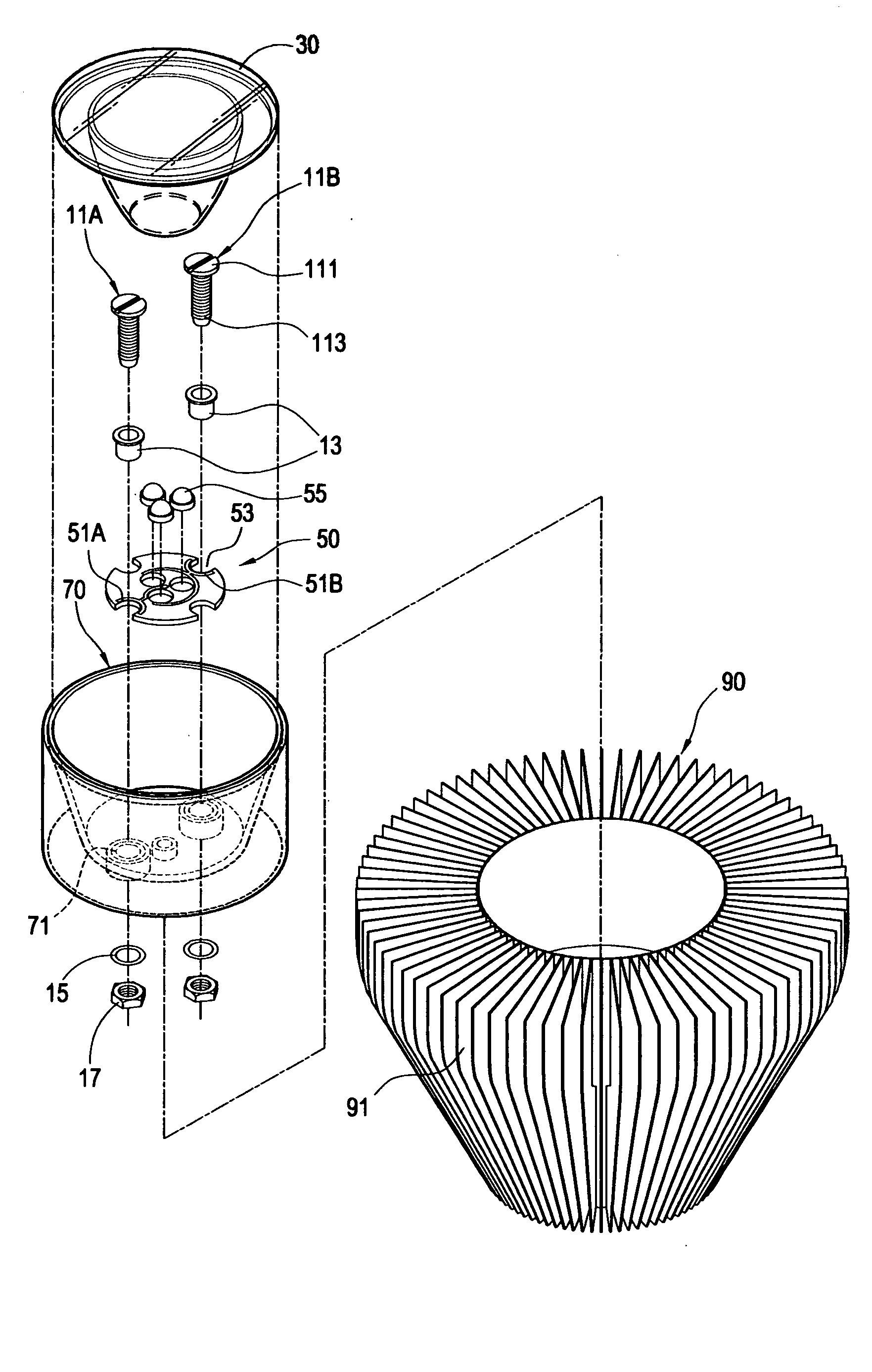
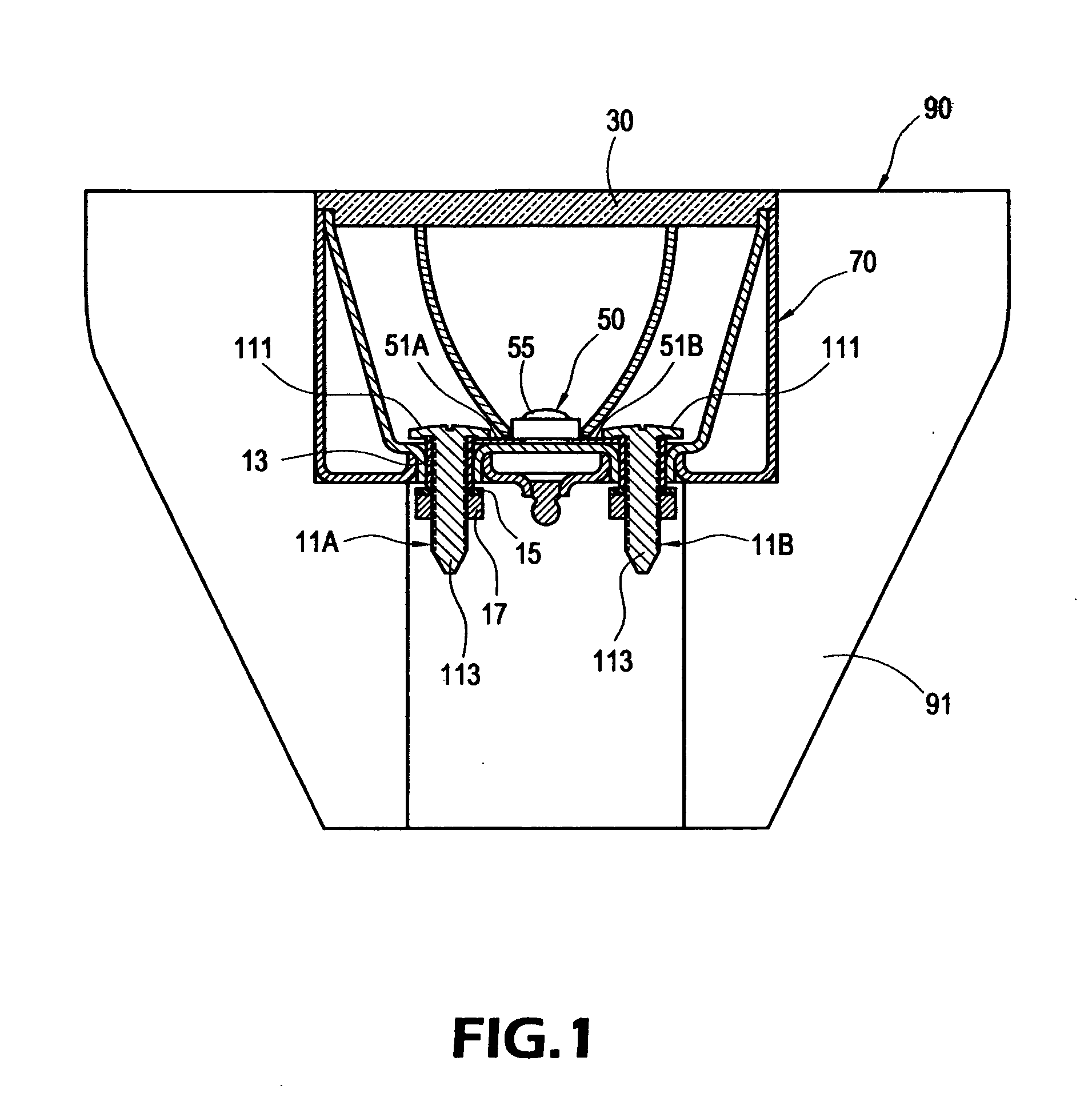
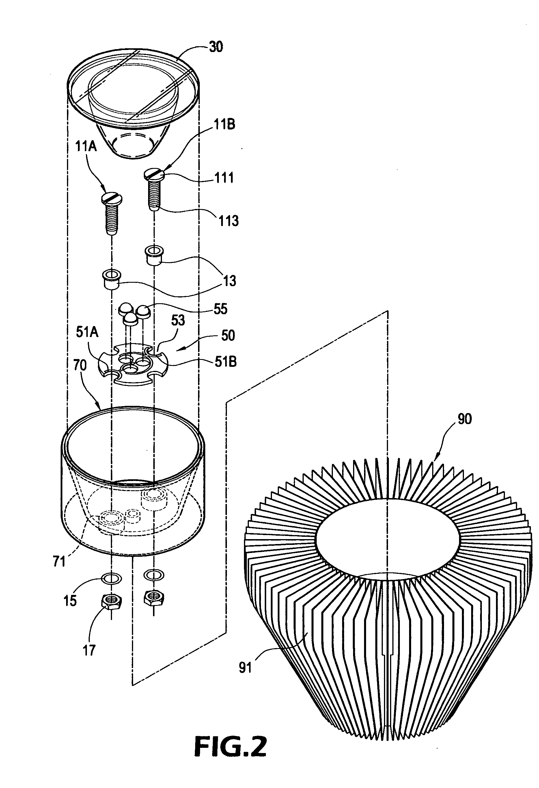
[0021] The present invention is intended to provide LED lamp with plate-type heat pipe. FIG. 1 shows a section view of the present invention and FIG. 2 shows a perspective view of the present invention. According to a preferred embodiment of the present invention, LED 55 is arranged on a support plate 50, and a first electrode pin 11A and a second electrode pin 11B are locked to an inner side of a mask-shaped plate-type heat pipe 70. A reflection shell 30 is arranged in front of the LED 55 to focus the light from the LED 55 to intensify the light. A through hole 71 is defined on the plate-type heat pipe 70 and through which the first electrode pin 11A and the second electrode pin 11B pass. The plate-type heat pipe 70 is placed within a lampshade 90 and the lampshade 90 comprises a plurality of heat-dissipation pla...


PUM


Abstract

An LED lamp conducting structure includes plate-type heat pipe of mask shape. A support plate mounted with LEDs is fixed on a plate-type heat pipe and then is placed within a lampshade. The plate-type heat pipe is made of metal with good thermal conductivity and has a plurality of through holes defined on bottom thereof. The support plate includes a plurality of electrode holes corresponding to the through holes. The anode contact and cathode contact of the LED are around the electrode hole. The contacts are exposed out of the support plate such that two screw-shaped electrode pins can be connected to the contacts after passing the electrode holes and the through holes. The electrode pins are locked to the plate-type heat pipe by screw such that the electrode pins have electrical connection with the contacts.

Description

BACKGROUND OF THE INVENTION [0001] 1. Field of the Invention [0002] The present invention relates to an LED lamp, especially to an LED lamp conducting structure with plate-type heat pipe. [0003] 2. Description of Prior Art [0004] Light emitting diode (LED) lamp generally comprises a set of LEDs, electrode pins of LED and a heat radiator. The LED generally comprises a first electrode pin and a second electrode pin for conducting electrical current to the LED. As the power and efficiency of LED are increased, heat dissipation is important issues. For example, heat pipe such as plate-type heat pipe (vapor chamber) is important. [0005] The plate-type heat pipe utilizes the principle of phase change for heat dissipation. The plate-type heat pipe generally comprises a heat-absorbing end and a condensation end. The heat-absorbing end is in contact with a heat source to conduct heat from the heat source to a working fluid to vaporize the working fluid. The vaporized working fluid moves to t...

Claims


Application Information

Patent Timeline
IPC IPC(8): F21V29/00H01J7/24
CPCF21K9/00F21V29/004F21V29/006F21V29/89F21V19/0055F21V29/773F21Y2101/02F21V29/51F21Y2115/10
Inventor WANG, PEI-CHOA
Owner PYROSWIFT HOLDING CO LIMITED
Learn More