
Thin film magnetic head, method of manufacturing the same, and magnetic recording head

a technology of magnetic recording head and film, which is applied in the direction of head with metal sheet core, data recording, instruments, etc., can solve the problems of unintentional emitted unnecessary magnetic flux, unintentional overwriting of information already recorded on the neighboring track, and preventing information from being recorded

Inactive Publication Date: 2007-10-11
SAE MAGNETICS (HK) LTD
View PDF5 Cites 4 Cited by
  • Summary
  • Abstract
  • Description
  • Claims
  • Application Information

AI Technical Summary

Benefits of technology

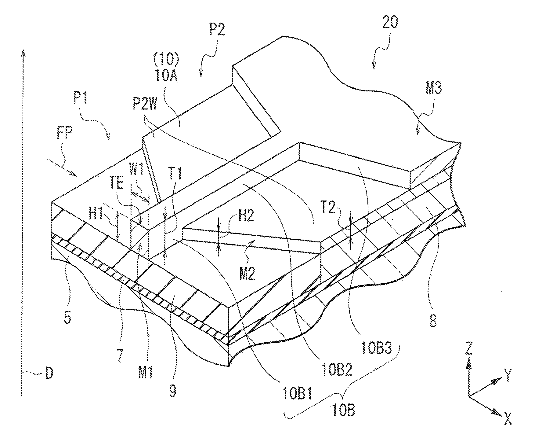
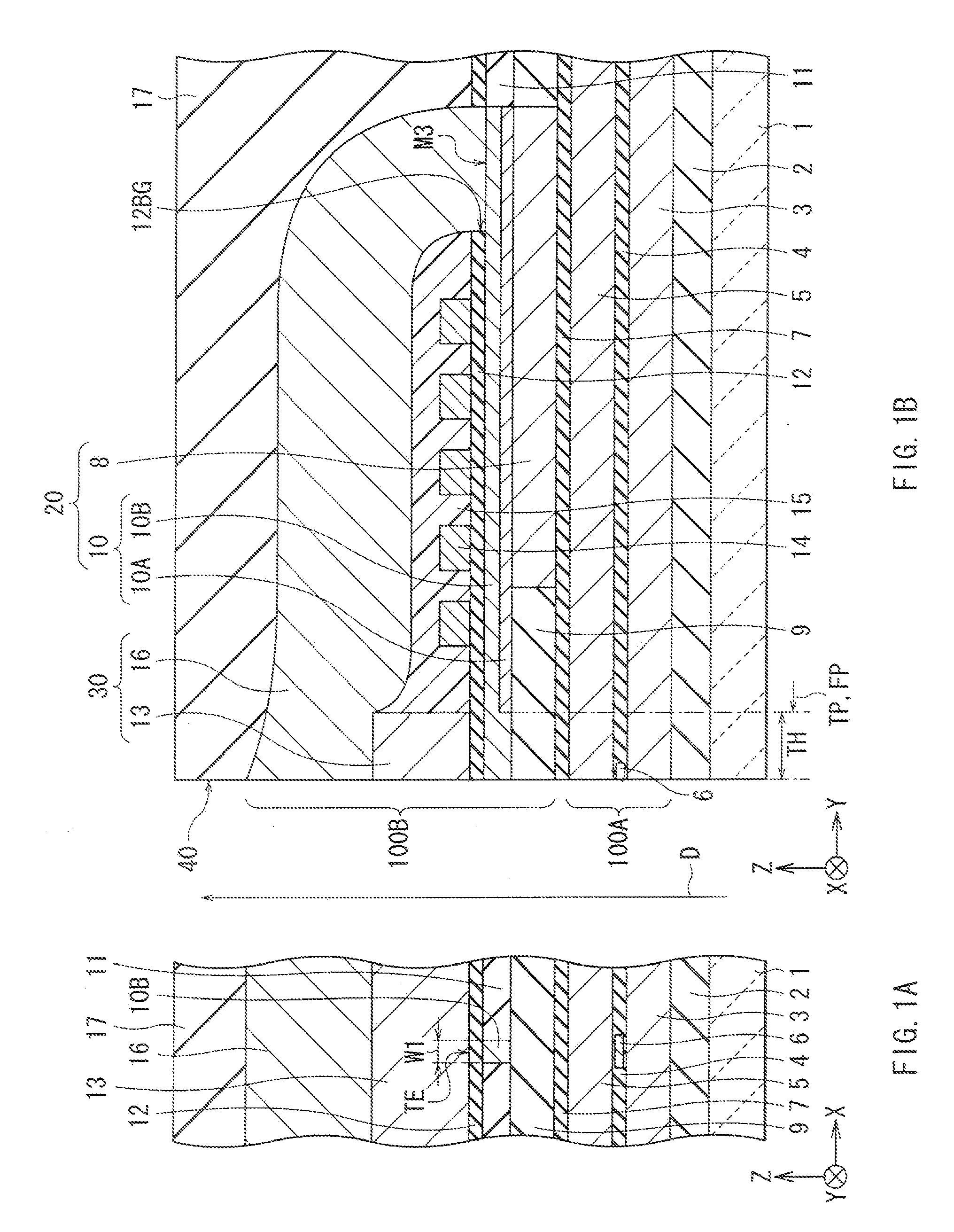
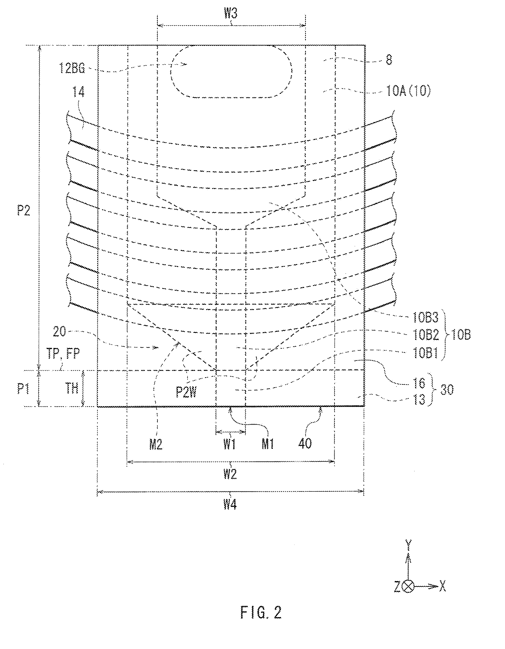
The present invention provides a thin film magnetic head that can prevent information recorded on a recording medium from being erased by unintentional writing to a neighboring track. The thin film magnetic head includes a thin film coil for generating a magnetic flux and a magnetic pole layer extending rearward from a recording-medium-facing surface and emitting the magnetic flux generated by the thin film coil towards the recording medium. The magnetic pole layer includes a uniform width portion having uniform width that specifies recording track width of the recording medium and including an exposed surface exposed on the recording-medium-facing surface and a wide portion coupled to the rear end of the uniform width portion and extending with width larger than the uniform width, with the height of the widened end surface in the wide portion being smaller than the height of the exposed surface in the uniform width portion. The thin film magnetic head can be manufactured stably and easily using existing manufacturing processes. The invention also provides a magnetic recording apparatus on which the thin film magnetic head is mounted, and the thin film magnetic head can prevent unintentional writing to a neighboring track and prevent information recorded on a recording medium from being erased.

Problems solved by technology

In addition, an unnecessary magnetic flux is unintentionally emitted to a neighboring track (a track adjacent to the track to be recorded) from the wide portion without passing through the uniform width portion.
Due to this, information already recorded on the neighboring track is unintentionally overwritten.
In sort, the phenomenon is a problem that recorded information is erased.
However, the conventional thin film magnetic head has a problem such that unintentional writing to a neighboring track cannot be sufficiently suppressed depending on a structural factor of the magnetic pole layer and there is the possibility that erasure of information recorded on a hard disk is not sufficiently prevented.

Method used


Image

  • Thin film magnetic head, method of manufacturing the same, and magnetic recording head
  • Thin film magnetic head, method of manufacturing the same, and magnetic recording head
  • Thin film magnetic head, method of manufacturing the same, and magnetic recording head

Examples


example

[0091] An example of the invention will now be described. Characteristics in the case where the thin film magnetic head of the invention shown in FIGS. 1A and 1B to FIG. 3 is mounted on the magnetic recording apparatus shown in FIGS. 15 and 16 and the recording process is performed in the embodiment were examined and the following results were obtained. The characteristics of the thin film magnetic head of the invention were examined on conditions that a flare distance (distance between the air bearing surface 40 and the flare point FP) is 0.3 μm, flare angle (angle between the extending direction of the front end portion 10B1 (Y-axis direction) and the widened end surface M2) is 70°, each of the width W1 and the thickness T1 of the front end portion 10B1 is 0.2 μm, and magnetomotive force of the thin film coil 14 is 150 mAT.

[0092] First, when the thickness ratio T2 / T1 was fixed to 0.5 and the unintentional writing state to a neighboring track was examined, the result shown in FIG....


PUM

PropertyMeasurementUnit
thicknessaaaaaaaaaa
widthaaaaaaaaaa
thicknessaaaaaaaaaa

Abstract

The present invention provides a thin film magnetic head capable of suppressing unintentional wiring to a neighboring track and preventing information recorded on a recording medium from being erased. A main magnetic pole layer is constructed so that height of a widened end surface in a lower main magnetic pole layer specifying a wide portion is smaller than height of an exposed surface in an upper main magnetic pole layer (front end portion) specifying a uniform width portion. Since the area of the widened end surface is narrowed with respect to the area of the exposed surface, even if an amount of magnetic flux flowing in the lower main magnetic pole layer increases at the time of recording information, as compared with the case where the height of the widened end surface is equal to the height of the exposed surface, unintentional emission of the magnetic flux flowing in the lower main magnetic pole layer from the widened end surface not via the upper main magnetic pole layer (front end portion) toward the recording medium is suppressed.

Description

[0001] The present application claims benefit of the Japanese Patent Application Number 2003-328632, filed on Sep. 19, 2003. BACKGROUND OF THE INVENTION [0002] 1. Field of the Invention [0003] The present invention relates to a thin film magnetic head having at least an inductive magnetic transducer for recording, a method of manufacturing the same, and a magnetic recording apparatus in which the thin film magnetic head is mounted. [0004] 2. Description of the Related Art [0005] In recent years, in association with improvement in areal density of a magnetic recording medium (for example, a hard disk), improvement in performance of a thin film magnetic head to be mounted on a magnetic recording apparatus (for example, a hard disk drive) is demanded. Known recording methods of a thin film magnetic head are a longitudinal recording method in which the orientation of a signal magnetic field is set to an in-plane direction (longitudinal direction) of a recording medium and a perpendicula...

Claims


Application Information

Patent Timeline
Patent Type & Authority Applications(United States)
IPC IPC(8): G11B5/127G11B5/147G11B5/31
CPCG11B5/312Y10T29/4906Y10T29/49043Y10T29/49041Y10T29/49032Y10T29/49044
Inventor MATONO, NAOTO
Owner SAE MAGNETICS (HK) LTD
Learn More