
Driving support apparatus

a technology of supporting apparatus and supporting rod, which is applied in the direction of braking system, television system, instruments, etc., can solve the problems of difficulty in providing proper information, and achieve the effect of improving the visibility of the object detected by the object detecting device, and improving the visibility of the obj

Inactive Publication Date: 2008-01-10
HONDA MOTOR CO LTD
View PDF2 Cites 63 Cited by
  • Summary
  • Abstract
  • Description
  • Claims
  • Application Information

AI Technical Summary

Benefits of technology

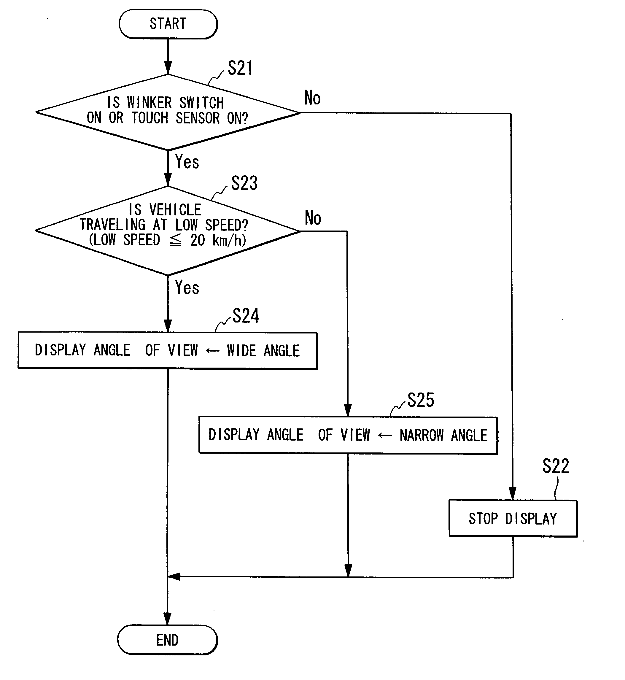
[0008]According to the above-described driving support apparatus, because it is possible to photograph side region of a present vehicle and rearward region of a present vehicle while altering an angle of view in accordance with the running state of the present vehicle, it is possible to set the quantity of external information that is required for a driving operation at a suitable quantity, and it is possible, for example, to prevent superfluous information being supplied unnecessarily, and prevent necessary information to be insufficient.
[0030]In this case, by performing at least one of an enlarged display, a highlighted display, and a display in the center of the display unit, of an object, it is possible to improve the visibility of the object and an object that is present in side region of or in rearward region of a vehicle can be made suitably visible to a driver.

Problems solved by technology

In the aforementioned conventional apparatus, because video image data of a predetermined photographic subject area is simply displayed on a monitor, if the quantity of information and the information contents required by the driver change in accordance with the running state of the vehicle, then it is difficult for the proper information to be provided.

Method used


Image

  • Driving support apparatus
  • Driving support apparatus
  • Driving support apparatus

Examples


Embodiment Construction

[0038]A driving support apparatus according to an embodiment of the present invention will now be described below with reference to the drawings.

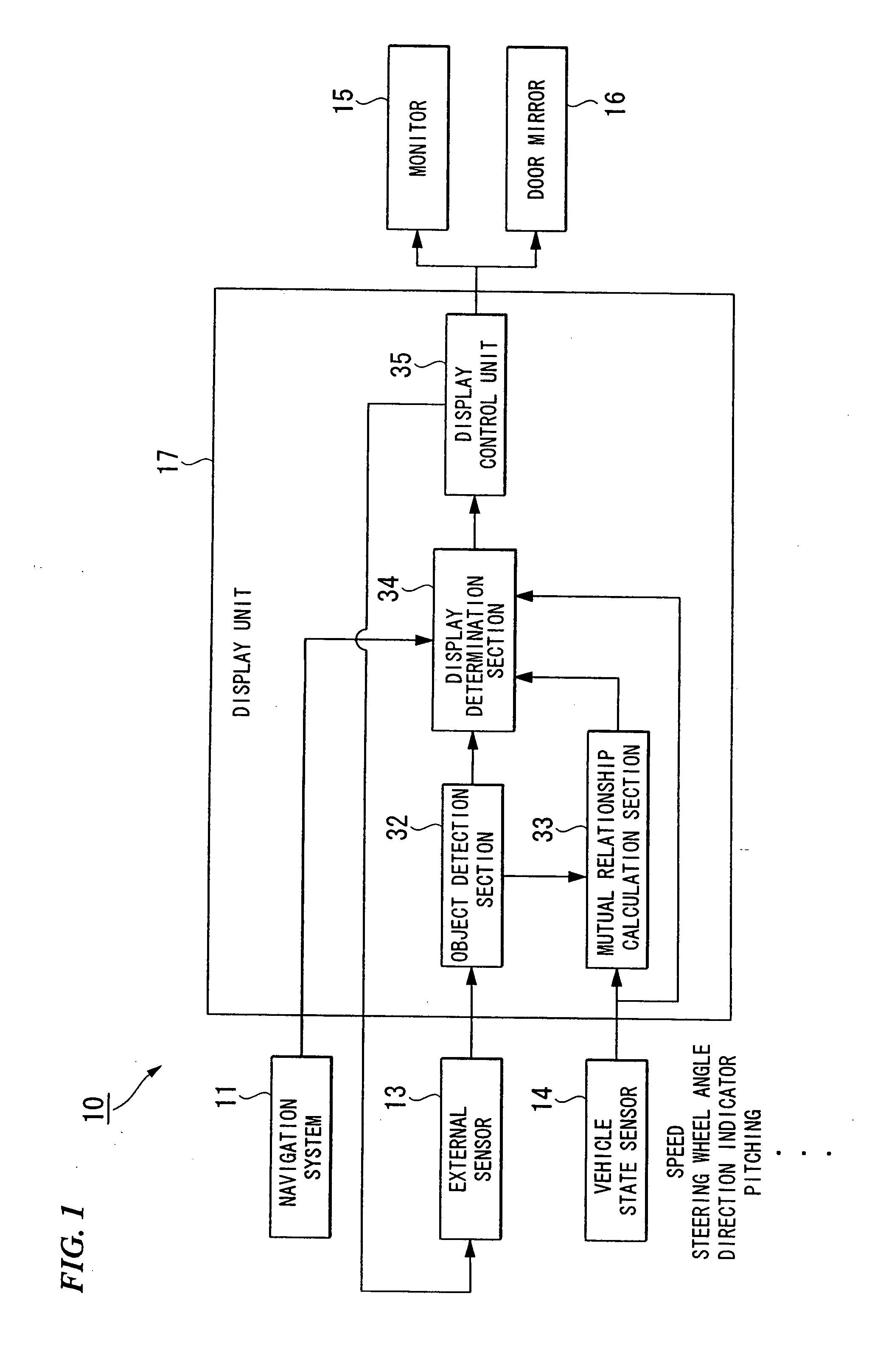
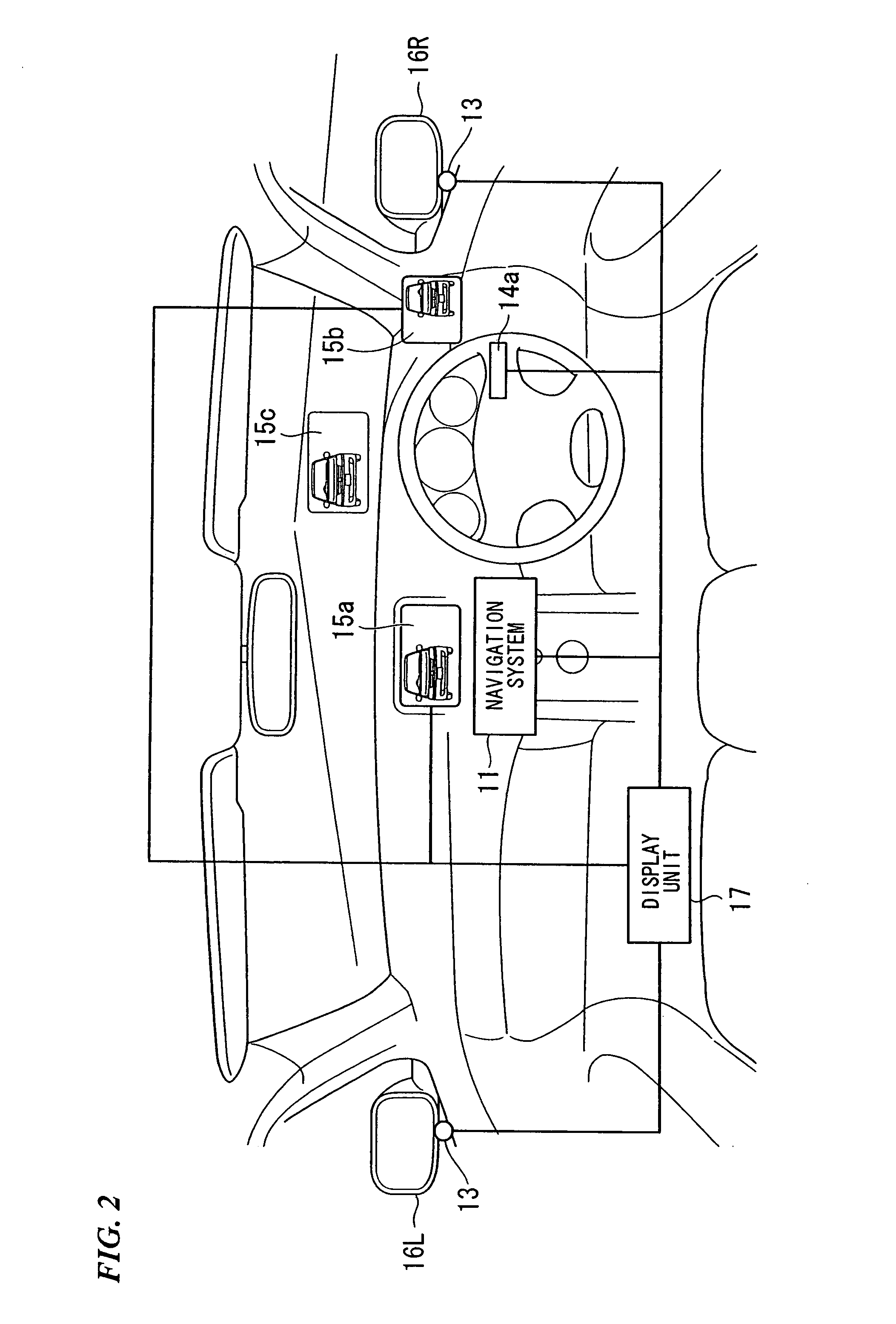
[0039]As is shown, for example, in FIG. 1, a driving support apparatus 10 according to the present embodiment includes a navigation system 11 (route setting device), an external sensor 13 (image sensing device), a vehicle state sensor 14 (speed measuring device), a monitor 15 (display unit), a door mirror 16, and a display unit 17.

[0040]The navigation system 11 determines the current position and traveling direction of a present vehicle based on measured results of positioning signals such as GPS (global positioning system) signals that are used to measure the position of a vehicle using artificial satellites, or based on various measured results from a gyro sensor and an acceleration sensor that are installed in the vehicle state sensor 14. In addition, based on the results of such determinations, the navigation system 11 performs map matc...


PUM


Abstract

A driving support apparatus includes: an image sensing device that photographs side region of a vehicle and rearward region of a vehicle while altering an angle of view; a display unit that displays video images photographed by the image sensing device so as to be visible to a driver of the vehicle; a display determination device that determines a running state of the vehicle, and determines whether or not an alteration of the display angle of view is required; and an angle of view adjustment device that switches the angle of view of the image sensing device, in accordance with a display method decided by the display determination device, between either one of a wide angle that enables the side region and the rearward region to be photographed, and a narrow angle that only allows the rearward region to be photographed.

Description

BACKGROUND OF THE INVENTION[0001]Priority is claimed on Japanese Patent Application No. 2006-185715, filed Jul. 5, 2006, the content of which is incorporated herein by reference.FIELD OF THE INVENTION[0002]The present invention relates to a driving support apparatus.DESCRIPTION OF RELATED ART[0003]Conventionally, an apparatus is known, that displays on a monitor video image data obtained by photographing rearward region of a vehicle using a camera (see, for example, Japanese Unexamined Patent Application, First Publication No. H09-71198).[0004]In the aforementioned conventional apparatus, because video image data of a predetermined photographic subject area is simply displayed on a monitor, if the quantity of information and the information contents required by the driver change in accordance with the running state of the vehicle, then it is difficult for the proper information to be provided.[0005]The present invention was conceived in view of the above-described circumstances, and...

Claims


Application Information

Patent Timeline
IPC IPC(8): G08G1/16
CPCB60R1/00B60R2300/105B60R2300/106B60R2300/205B60R2300/207G08G1/16B60R2300/306B60R2300/70B60R2300/8026B60R2300/8033B60R2300/8093B60R2300/302G08G1/166G08G1/167B60R1/30B60R1/26B60R1/28
Inventor WATANABE, TAKASHIOSHIDA, KEISUGIMOTO, YOICHI
Owner HONDA MOTOR CO LTD
Learn More