
Start-up control for internal combustion engine

a technology of effective compression ratio and internal combustion engine, which is applied in the direction of engine starters, electric control, machines/engines, etc., can solve the problems of low effective compression ratio, increased effective compression ratio, so as to reduce effective compression ratio and increase effective compression ratio

Inactive Publication Date: 2007-10-11
NISSAN MOTOR CO LTD
View PDF7 Cites 20 Cited by
  • Summary
  • Abstract
  • Description
  • Claims
  • Application Information

AI Technical Summary

Benefits of technology

The invention is a start-up control device for an internal combustion engine that prevents combustion defects during start-up. It detects the engine rotation speed and other operating parameters, and modifies the effective compression ratio of the engine from a start-up position to a normal position based on the engine rotation speed. This prevents misfires and combustion defects during start-up, even at high altitudes or low temperatures. The device includes a fuel supply device and a starter motor. The technical effect of this invention is to improve the reliability and efficiency of internal combustion engines during start-up.

Problems solved by technology

In this type of internal combustion engine, a response delay occurs when modifying the valve opening timing from the retarded position to the normal position, and as a result, the effective compression ratio may not increase for a while even when the engine rotation speed increases beyond the resonance rotation speed range during start-up of the internal combustion engine.
However, if fuel injection is begun while the effective compression ratio remains small, a combustion defect such as a misfire may occur.
At low temperatures or high altitudes where the air pressure is low, a misfire is particularly likely to occur when fuel injection is performed at a small effective compression ratio.

Method used


Image

  • Start-up control for internal combustion engine
  • Start-up control for internal combustion engine
  • Start-up control for internal combustion engine

Examples


second embodiment

[0087]Next, referring to FIGS. 8, 9, 10A-10C, 11A-11C, 12A-12C, 13A and 13B, 14A-14C, and 15A and 15B, this invention will be described.

[0088]In this embodiment, a routine shown in FIG. 8 is executed in place of the routine of the first embodiment, shown in FIG. 4, and a subroutine shown in FIG. 9 is executed in place of the subroutine shown in FIG. 5. Other constitutions of a start-up control device are identical to those of the first embodiment.

[0089]Referring to FIG. 8, the processing content of the step S401 and the steps S404-S406 is identical to that of the routine shown in FIG. 4.

[0090]In a step S502, the controller 104 reads two sensor values selected from the atmospheric pressure PA, the intake air temperature TA, the engine cooling water temperature TW, the fuel pressure P_Rail, and the effective compression ratio modifying mechanism operating angle V_Ang.

[0091]In a step S503, the controller 104 determines whether or not combustion is possible by executing the subroutine s...

first embodiment

[0110]In the step S1202, the controller 104 accesses the secondary determination map having the characteristics shown in FIG. 11B, in which the effective compression ratio modifying mechanism operating angle V_Ang and the intake air temperature TA used as the secondary determination parameter serve as parameters, from the ROM. From the effective compression ratio modifying mechanism operating angle V_Ang and the intake air temperature TA, the controller 104 determines that the operating condition of the internal combustion engine 101 corresponds to a point E in the figure. The point E is included in the combustion impossible region, and therefore the controller 104 outputs a fuel supply prohibition command in the step S1104 and terminates the subroutine. Processing following termination of the subroutine is identical to that of the

[0111]Hence, the controller 104 continues to crank the engine 101 using the starter motor 102 without injecting fuel from the fuel injector 207 until the ...

third embodiment

[0133]Referring to FIGS. 16-19, FIGS. 20A-20G, FIGS. 21A-21C, and FIGS. 22A-22C, this invention will be described.

[0134]This embodiment is executed in combination with the first embodiment or second embodiment. More specifically, a determination as to whether or not the internal combustion engine 101 is capable of combustion is made on the basis of the engine rotation speed NE and at least one other parameter indicating the operating condition of the internal combustion engine 101, and fuel supply by the fuel injector 207 is performed in accordance with the determination result. Simultaneously in this embodiment, the time required for combustion to become possible from the beginning of cranking of the internal combustion engine 101 is estimated, and the rotation speed increase rate of the starter motor 102 is varied in accordance with the estimation result.

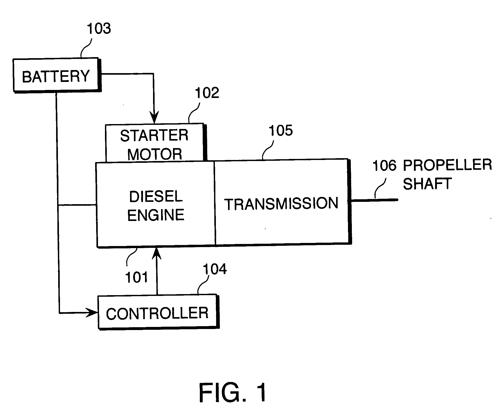
[0135]Referring to FIG. 16, this embodiment is applied to a hybrid drive electric vehicle.

[0136]The hybrid drive electric vehicl...


PUM


Abstract

An internal combustion engine (101, 601, 901) alters an effective compression ratio from an effective compression ratio for a start-up operation to a larger effective compression ratio for a normal operation when an engine rotation speed (NE) increases beyond a resonance rotation speed region during cranking. A controller (104, 610, 910) determines whether or not the engine (101, 601, 901) has reached a combustion possible state on the basis of the engine rotation speed (NE) during cranking and an operating parameter (PA, TA, TW, P_Rail, V_Ang) other than the engine rotation speed (NE) (S1102, S1202, S1204). When the determination is negative, the controller (104, 610, 910) inhibits fuel supply to the engine (101, 601, 901) by a fuel supply device (207), even when the engine rotation speed has increased beyond the resonance rotation speed region (S406). In so doing, a combustion defect such as a misfire is prevented.

Description

FIELD OF THE INVENTION[0001]This invention relates to start-up control of a variable effective compression ratio internal combustion engine, based on a resonance rotation speed.BACKGROUND OF THE INVENTION[0002]An internal combustion engine for a vehicle has a specific resonance rotation speed region that is dependent on an engine mount and a drive system damper.[0003]JP2001-123857A, published by the Japan Patent Office in 2001, proposes a variable effective compression ratio internal combustion engine for a vehicle in which the variable compression ratio of the internal combustion engine is suppressed to be small in the resonance rotation speed region.[0004]In this prior art, when the rotation speed is within the resonance rotation speed range during start-up of the internal combustion engine, torque variation is reduced by suppressing the effective compression ratio of the internal combustion engine to be small. By reducing torque variation during start-up, the amplitude of torsion...

Claims


Application Information

Patent Timeline
Patent Type & Authority Applications(United States)
IPC IPC(8): F02M1/00F01L13/08F02B75/02B60K6/48B60W10/08F02N99/00B60W20/00F02D13/02F02D41/06F02D45/00F02N11/08
CPCF01L1/34F01L2800/01F02D13/0276F02D15/04F02D17/04F02D41/062Y02T10/18F02N11/08F02N19/004F02N2011/0896F02N2300/102F02N2300/104F02N11/006Y02T10/12
Inventor SHIINO, TOSHIKAZUSUZUKI, HIROYUKITATARA, TOMOHIKO
Owner NISSAN MOTOR CO LTD
Learn More