
Inflatable structure

a technology of inflatable structures and floating parts, which is applied in the field of inflatable structures, can solve the problems of a large amount of time and effort, a large amount of operator's memory, and the whole boat would deflate and sink

Inactive Publication Date: 2007-10-04
NAUTIC & ART
View PDF16 Cites 13 Cited by
  • Summary
  • Abstract
  • Description
  • Claims
  • Application Information

AI Technical Summary

Benefits of technology

[0008] It is an object of the present invention to provide a watercraft that may be rapidly inflated through one inflation valve.
[0010] It is yet another object of the present invention to provide a watercraft having many chambers that can all be inflated through the same inflation valve while still retaining a level of isolation from one another in case of puncture through the use of check valves.
[0013] Advantageously, all of the watercraft may be inflated by inflating from only one inflation valve. This greatly diminishes manipulation, further reducing the reaction time of a rescue team. Furthermore, because the check valves are concealed inside the watercraft, it is not possible to break them or to get injured on them. Moreover, because check valves open and close automatically, they do not require an operator to intervene when inflating the watercraft, or when a chamber gets punctured. It is also impossible to forget to close the valves, which could lead to all chambers leaking air in case one of them gets of punctured.

Problems solved by technology

This is a tedious process which requires a great deal of time and effort since the chamber must be inflated, the pressure checked, further inflation and / or deflation carried out and the process must be repeated in order to arrive at the appropriate pressure.
However, the disadvantage of this method is that the operator needs to remember to open the valves before inflating and close them afterwards.
Otherwise, in case a chamber gets punctured, the whole boat would deflate and sink.
Moreover, it takes time to open the valves and then close them, which is not a luxury one can afford when the boat is used during urgent rescue missions.
Furthermore, the crew or the person being rescued may easily catch his clothes or limbs on the exposed valves.
The raft described in this patent uses two inflation valves rather than just one, which is an inconvenient when a rescue crew needs to inflate the raft in a hurry.
Moreover, this raft has no inflatable deck and no openings at water level, therefore not being well adapted for rescue operations where imperiled persons need to be rescued from water level and rescuers need to stand up on the deck.
Although adapted for the rescue of imperiled persons, this raft may not be easily and rapidly inflated because it requires that the two chambers plus the deck be inflated separately.
This forces the operator to connect its source of compressed air at all three different places, losing precious time in the manipulation.

Method used


Image

  • Inflatable structure
  • Inflatable structure
  • Inflatable structure

Examples


Embodiment Construction

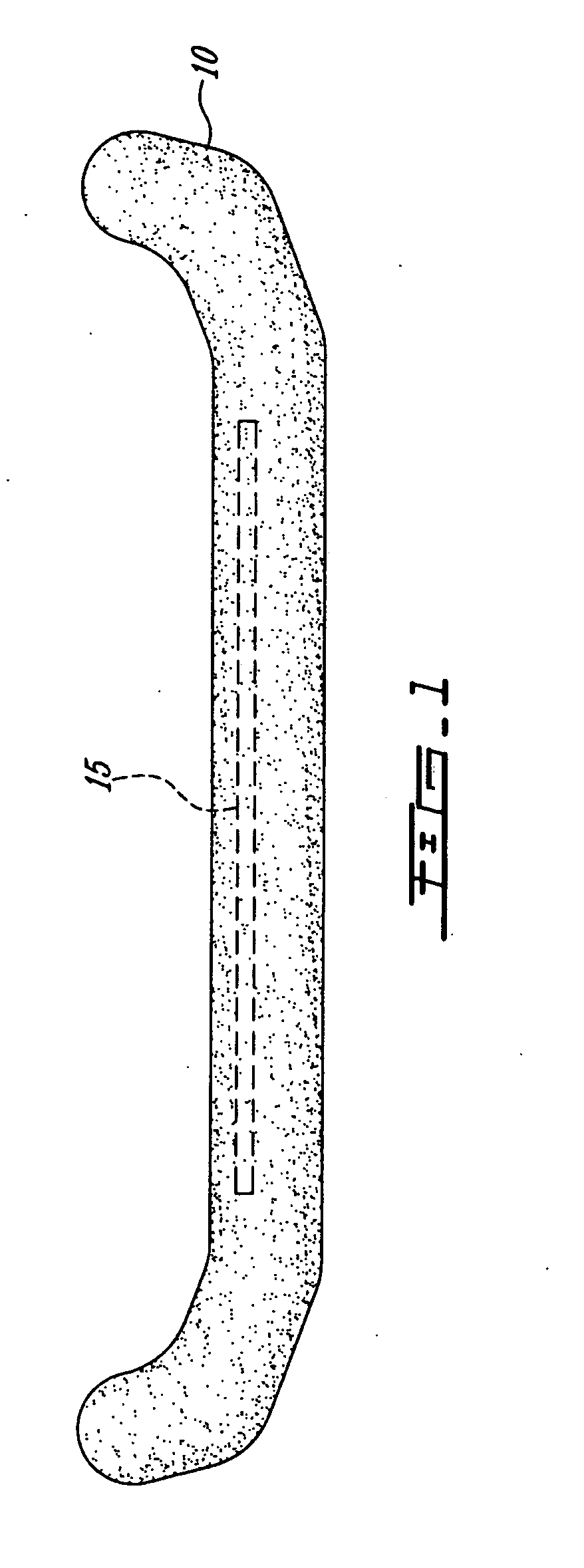
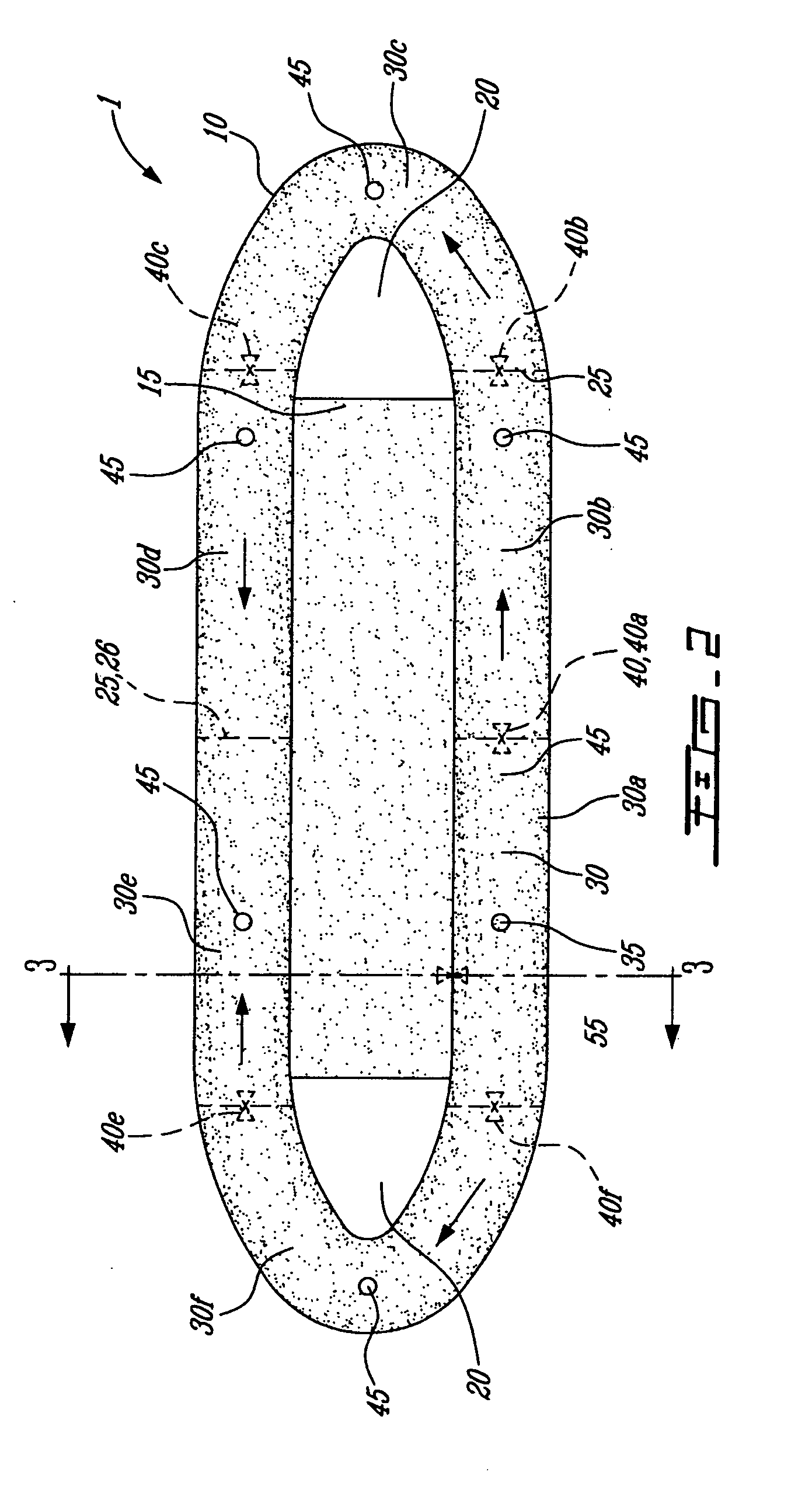
[0019] The present invention will be described with regards to a particular application, namely a rescue raft. FIG. 1 depicts the rescue raft 1 of the invention. The raft comprises an inflatable tube 10, an inflatable deck 15 and two openings 20. The tube 10 encircles the deck 15 and both openings 20. Bulkheads 25 are located inside the tube 10 to divide it in a plurality of chambers 30. A single inflation valve 35 is located at one place on the raft 1, either on the wall of a chamber 30, or on the wall of deck 15. Preferably, it is located in a place where an operator may quickly and easily reach it, such as the top of the wall of a chamber 30 for example. Each chamber 30 and the deck 15 comprise a deflation valve 45.

[0020] Check valves 40 are provided to allow the air to communicate from one chamber 30 to another and to the deck 15. The check valves may be located outside of the tube 10, but are preferably located inside the tube 10. Check valves 40 in between chambers are locate...


PUM


Abstract

The present invention relates to an inflatable structure comprising an inflatable frame and a single inflation valve. The inflatable frame has at least two chambers in fluid communication with at least one other chamber through a check valve, whereby the chambers are inflated through the inflation valve.

Description

FIELD OF THE INVENTION [0001] The present invention relates to the field of inflatable structures. More particularly, the invention relates to an inflation system for an inflatable watercraft adapted for rescue operations. BACKGROUND OF THE INVENTION [0002] Numerous examples of inflatable boats are known in the art. Many of these inflatable boats are formed, for safety reasons, from at least two separate inflatable chambers which typically form the side of the boat. [0003] An example of a collapsible inflatable boat is shown in Design Pat. No. 151,467. In this patent, the boat is formed from three separate inflatable chambers each of which has its own valve member for inflating and deflating the chambers. In such a boat, it is necessary to inflate and / or deflate each chamber separately. This is a tedious process which requires a great deal of time and effort since the chamber must be inflated, the pressure checked, further inflation and / or deflation carried out and the process must ...

Claims


Application Information

Patent Timeline
IPC IPC(8): B63B35/58
CPCB63B7/08
Inventor LAROCHELLE, LUCLAROCHELLE, SERGE
Owner NAUTIC & ART
Learn More